I am replacing the input and feedback caps on my acurus A250. C7 is a 220uf 25v non polarized cap. What is the best cap to replace that with these days? It is too expensive to try and replace with a film cap. I have been reading up on Muse es bi-polar or possibly running two Elna Silmic II's in series to make my own bi=polar. one suggestion was to use the Muse and bypass with a film cap. What is the consensus on this?
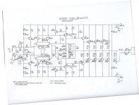
here is the schematic, i really would like to implement a dc servo but do not have the knowledge to do so. Anyone care to give me a how to ") short of that, it looks like ES muse or doubling a pair of Nichicon KZ's or elna silmic II's.
short of that, it looks like ES muse or doubling a pair of Nichicon KZ's or elna silmic II's.
From the schematic, the designer already bypassed these two caps (c2 and c7) with film caps (c1 and c6). Wima MKS caps were used. I am going to replace those as well with WIMA MKP.
short of that, it looks like ES muse or doubling a pair of Nichicon KZ's or elna silmic II's.From the schematic, the designer already bypassed these two caps (c2 and c7) with film caps (c1 and c6). Wima MKS caps were used. I am going to replace those as well with WIMA MKP.
ok so here is what I have come up with so far.
input coupling cap C2 - 10uf Claritycap ESA
input bypass cap C1 - .1uf vishay MKP 1837
feedback cap C7 - 220uf Nichicon Muse ES
feedback bypass C6 - undecided (possibles: Wima mkp4 or MKP10 or open to suggestion)
c12 .1uf - vishay 1837 or wima mkp4 or mkp10
input coupling cap C2 - 10uf Claritycap ESA
input bypass cap C1 - .1uf vishay MKP 1837
feedback cap C7 - 220uf Nichicon Muse ES
feedback bypass C6 - undecided (possibles: Wima mkp4 or MKP10 or open to suggestion)
c12 .1uf - vishay 1837 or wima mkp4 or mkp10
OK, where is it?here is the schematic.....
Anyways, you probably won't get much joy from swapping good caps that are not passing or bearing directly on the signal. Your input cap. could be a problem for size and quality. An ideal 10 uF MKP is way big and wortks like an aerial for RFI & EMI but it may be perfectly reasonable to downsize going from electrolytic to film types. Just be careful fitting out with your wish list of bits when size and lead spacings change.
Last edited:
I used to think that the feedback cap had signal across it and so when a designer said fit this or that in that location I always did what I was told.
Only after joining this Forum did I come to realise that the NFB cap has virtually no signal across it. Measure the AC and/or the DC across the cap if you don't believe me.
If the cap is properly selected to ensure it has no audio signal across it in all normal operation then it can contribute no distortion to the audio output.
If you select the wrong capacitor for the duty then it may have voltage across it and then it may contribute to output distortion.
Self was the first to draw my attention to that and it was following on from his prompting that I came to my current conclusions.
Make sure the NFB cap has no significant signal across it.
Once you achieve that you may come to the same conclusions as me:
I cannot hear the difference in swapping expensive or exotic caps for the normal commercial grade electrolytic in the NFB loop, when that cap is selected to have no significant signal across it.
Last edited:
OK, where is it? oops
ok, the input cap now is a 10uf non polar electrolytic. I have been told that this is the most important cap to swap to a film type. My options are either keep using an electrolytic such as the Nichicon ES Muse or change to the Claritycap ESA MKP which is axial and much bigger.(there are better film caps but money was much more) All of the MKP caps are much bigger in 10uf. I know there is the possibility of picking up noise. The questions is, if I shield the larger Film cap to keep noise out, will it be worth the effort over the Muse bi-polar electrolytic option. This cap is also bypassed from factory with a .1uf Wima MKS. I am switching the stock MKS for a Vishay 1837. Vishay only cost $1 so no brainer. The only cap that is expensive is the Claritycap at $20 ea. I need 2. The feedback cap is 220uf NP and will remain an electrolytic and I will be using the Muse BI-polar there. It gets bipassed with a .47uf cap and I will use a Wima MKP4 as it is the same size as the MKS that is there now. The mkp10 is larger so its out. There is also the one other .1uf cap (c12) which I don't know what it does but for $1, it is getting a 1837 vishay
ok, the input cap now is a 10uf non polar electrolytic. I have been told that this is the most important cap to swap to a film type. My options are either keep using an electrolytic such as the Nichicon ES Muse or change to the Claritycap ESA MKP which is axial and much bigger.(there are better film caps but money was much more) All of the MKP caps are much bigger in 10uf. I know there is the possibility of picking up noise. The questions is, if I shield the larger Film cap to keep noise out, will it be worth the effort over the Muse bi-polar electrolytic option. This cap is also bypassed from factory with a .1uf Wima MKS. I am switching the stock MKS for a Vishay 1837. Vishay only cost $1 so no brainer. The only cap that is expensive is the Claritycap at $20 ea. I need 2. The feedback cap is 220uf NP and will remain an electrolytic and I will be using the Muse BI-polar there. It gets bipassed with a .47uf cap and I will use a Wima MKP4 as it is the same size as the MKS that is there now. The mkp10 is larger so its out. There is also the one other .1uf cap (c12) which I don't know what it does but for $1, it is getting a 1837 vishay
Attachments
Last edited:
That's true in my experience too.OK, where is it? oops
ok, the input cap now is a 10uf non polar electrolytic. I have been told that this is the most important cap to swap to a film type. My options are either keep using an electrolytic such as the Nichicon ES Muse or change to the Claritycap ESA MKP which is axial and much bigger.....
Thanks for the schematic - some nice features there. The 10uf value is not necessary for an input impedance around 50k so I think you could use a smaller, cheaper part without bass penalty. It is normal to use much higher electrolytic values to avoid the bass distortion they introduce. The bypass cap does nothing to help there but it will probably sound fair, if a little weak in the bass, on its own - try it and listen for deep bass.
Use a 2.2uF MKP there initially, as these are inexpensive and tolerably proportioned. Brand is irrelevant unless you are considering specialty, unique high-end products with stellar prices.
AndrewT's comment on the feedback cap is fair and the issue of no DC across it considered poor in some circles. Many types have been tried there. Why not a Sanyo OSCON? They are rated to only low voltage in that capacitance range but can be protected by a couple of 5c inverse parallel diodes across them - if you fear the output stage may fail and expose it to rail voltage. It hasn't happened yet, apparently
M,
the 10uF is followed by 22k to ground this gives an input filter RC time constant of 220ms.
The NFB is 680r & 220uF. This is a filter RC time constant of ~150ms.
These two time constants have been inadvertently swapped because the designer did not think it important enough to avoid AC voltage across the NFB capacitor.
I strongly suggest you at least listen to the amp with the RC swapped. i.e make the input cap smaller to reduce the time constant to ~100ms.
IMHO, a more useful way to look at it is in terms of frequency response.I could use a 4.7uf input cap and get a RC time constant of 103.4ms. Does that sound right? A 2.2uf would be 48.4ms. Which would be the better choice?
1uF => -3dB @ 7Hz, -1dB @ 14Hz, -0.1dB @ 45Hz
2.2uF => -3dB @ 3.2Hz, -1dB @ 6.2Hz, -0.1dB @ 21Hz
4.7uF => -3dB @ 1.5Hz, -1dB @ 2.9Hz, -0.1dB @ 9.6Hz
btw, That's an interesting doodle on the right side of the schematic, after the "output". Does it indicate you've got the loudspeaker cable looped through a ferrite ring or something?
Those time constants give -3dB points of ~10 and 20 Hz respectively. It will depend on your speaker capabilities whether it is "feelable" more than audible. In recent times, design has shifted to keeping bandwidth defined at the input rather than in the amp and increasing distortion. As AndrewT pointed out, the design doesn't address that problem but few older amps do anyway. They still work and people like them.
If you need to restore the -3dB roll-off point to the 5Hz region, you then need the huge 10uF cap and increase the feedback cap to 470uF or much more, to compensate.
Electrolytics need to be 5-10x larger than lowest frequency requires it to be for a flat response, in order to avoid distortion and that's a good reason for not using them in filters, because that condition can obviously be self-defeating.
Andrew also brought my attention to this being closer to 22k resistance so I would not go smaller than 2.2 uF on test as this will then considerably cut the response. For the cost of 1 or 2 cheap MKPs, test and learn rather than accept opinion as right or wrong about ultra-low frequency limitations. DIY!
PS - Godfrey, didn't see your post but I think that's an output relay.
Last edited:
Very much so.For the cost of 1 or 2 cheap MKPs, test and learn rather than accept opinion as right or wrong about ultra-low frequency limitations. DIY!
That's what I did.
I was surprised how deep the bass changes would go and be audible with F-3dB set way below 20Hz.
I came to MY conclusion that ~90ms as the input filter worked for my amplifiers and speakers. I could not hear any extra information by going lower.
I could hear differences at 2 octaves higher. I was not sure if I could hear differences @ 1octave higher. Maybe I could have got away with 50ms, but what if I got speakers that extended an octave or more down towards sub-bass?
You don't need to change the cap alone. You can change the resistor. It's an RC time constant that defines the filter characteristic.
Eg.
start with a 1uF high quality (commercial grade) polypropylene DC blocking cap. Fit a 200k resistor on slightly long legs soldered into the PCB.
Add various parallel resistors (clipped or soldered to those long legs, or on the underside) to bring Rin down from 200k to 10k and listen to what effect these RC changes have made. Are they audible? Do you have a preference? Do different Speakers, or different Sources, or different moods change your preferences?
No, about 6 times lower than that.Those time constants give -3dB points of ~10 and 20 Hz respectively.
F = 1 / (2*Pi*R*C)
I think the values I gave above are correct.
btw guys. I'm not an engineer or anything so a lot of these principles are over my head but i am a quick study. I appreciate the time you are taking to explain in a way that I can put it to use and I research on the side to better understand the concepts.
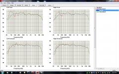
I happen to have a graph from my Anthem room correction software from my preamp. It shows the frequency response of my speakers. they roll off pretty good above 12k for some reason. Fronts are KEF Reference model Two's. These are powered by the Acurus A250. My rears are KEFq80's which use the same tweeter. Center is KEK Ref. 100. Same tweeter again. They are a soft dome.
Looking at these graphs, what would be a good place to start? the Anthem is able to boost or cut frequencies only up to 5k. Above that it can't control. The rear speakers are hooked to an Adcom 2535 so I don't think the roll off has anything to do with amps. the blue line is the target curve and the other two plots are before correction and after correction to achieve target.
Attachments
Last edited:
Quite so, thanks and sorry guys - senior moment, or that's my excuse.No, about 6 times lower than that.
F = 1 / (2*Pi*R*C).
ok, so I see the trend. The smaller the cap the higher the frequency for the -3db down point but the lower the time constant. By raising the value of the cap you raise the time constant and lower the -3db down point. My mains have two 6.5" coupled subs. They can go pretty low but I also have a 12" sub that I use. If listening to movies, it is always on and when listening to stereo, I can turn it on or off in the Anthem. When on, it applies a 60hz high pass to the mains and when off, it runs the mains full band width. I will try different caps but the 4.7uf value looks pretty good from both a TC and frequency stand point. I will get something in the 3uf range as well.
The late John Linsley-Hood had views on the influence of components and circuitry and published his view in 3 articles entitled "Audio Amplifier Design, Engineering or Alchemy".
These appeared in "Everyday with Practical Electronics" magazine between August and October 1993. I have kept copies of the articles.
In general Hood preferred plastic capacitors over electrolytic types where-ever he could use them. With a 220uf cap in the decoupling arm of a feedback loop an electrolytic is necessary for practical reasons. Others have discussed the low frequency roll off this cap has in the feedback system. The gain in the level audio range is given by (22K+680R) divided by 680R. Hood points out that electrolytic capacitors have an element of parasitic resistance in series with the capacitance he calls "Rx" which "is a long way from being an ideal resistor, and its value is likely to be voltage, temperature, polarity and frequency dependent, as well as being influenced even by the shape of the a.c. applied to it." He continues, "since Rx is likely to be a significant fraction of (680R), and will in consequence, have an effect on the gain of the system, the remarkable thing is that the non-linearity of the series loss resistance of, for example, an electrolytic capacitor used in this position , has so small an effect on Total Harmonic Distortion (THD), of the amplifier, measured at, say 1kHz."
"If one measures the intermodulation distortion, (IMD), effects produced when the amplifier is driven by several simultaneous input signals, using a spectrum analyser to track down the spurious signals, the differences between one type of d.c blocking capacitor and another used in the negative feedback loop, due to various real-life imperfections in its operation, are more easily seen. Changing the capacitor type of capacitor used in this position does indeed affect sound quality which is what the IMD measurements will point out, especially if one of the input signal used in the test is a square wave type."
The Australian Silicon Chip magazine published articles last year for a 3rd edition of their LD(low distortion amplifier) using all the current technical expedients to deliver 135 Watts R.M.S into 8 ohms with measured THD typically .0006% from 20Hz-20kHz.
One of the modifications made was to increase the feedback blocking cap from 220 uF to 1000uF. Claims "... which reduces distortion and flattens the response at vary low frequencies. It also slightly improves the signal-to-noise ratio". The series resistor in the decoupling arm is 510R. The resistor at the amplifier input is 12K. The input cap is a 47uF non polar type. From the accompanyin photo's the caps appear to be standard "off the shelf" parts.
I am offering the foregoing "Without Prejudice". The information may or may not be useful.
Michael Jonassen
- Status
- This old topic is closed. If you want to reopen this topic, contact a moderator using the "Report Post" button.
- Home
- Amplifiers
- Solid State
- replacement 220uf bi-polar options