I’m building an amp with four channels I one box (For biamping and/or bridging)
For the power supply I’ll be using 2*500 VA torrid transformers. But the question is how to do the mains cabling?
I have a capacitorbank of 240mF that needs to get started when I turn on the amp. This made me think about how you all make the connection on the primary side of your transformers on bigger amps.
I also wonder about what type of switches you use for your mains?
My plan is to have a stand by 12 V inside the box to power a series of relays for the mains and amp output relays. The mains will run thru a series resistor to the primary side of the transformer, and after a second or so this resistor will be shorted out to make the mains be coupled directly to the primary side of the torrid.
I’m making an interface to connect the amp to my B&O preamplifier; this controls power up and muting of the amp. This could also be used to control the amp via some small switches and there by not having to worry about high current switches?
Any comments and ideas are welcome
Thanks
\Jens
li_gangyi said:Guess there are no better ways...only a clean relay will do...
well u can use scr's or triacs instead of relays ,its quiet and u dont have to worry how long will they last , but those are far more expensive
SCRs...cool stuff...how many amps will they have to be rated...they aren't really expensive...especially sice you can get some samples from On-semi...but that would mean a power on the gate...meaning it would be close to the full live potential?? or does it just have to be a small signal to switch it on???

Hmmm....but still will there be a "super-;ong lasting" relay?? seems they are prone to dying...ahd one crap out in the protection of my amp...took me hours to find it...coz I didn't expect it to fail...replaced the whole channel...just to find that the relay was the culprit...had 2 internal contacts...only 1 was faulty...wonder why...
there are scrs available for 1KW of power and higher ,
it works like a switch so the power dissipation is low
noise ? well some amps sensitive to noise , my is not")
i'm using voltage regs for input stages
plus most amps that got a current source in the input stage LTP are not sensitive to small noise generated by the power supply
it works like a switch so the power dissipation is low
noise ? well some amps sensitive to noise , my is not
i'm using voltage regs for input stages
plus most amps that got a current source in the input stage LTP are not sensitive to small noise generated by the power supply
triacs/scr`s are more reliable than relays as I use both in my controls and like any electronic component they have to be treated as such......the on/off cycle life of a triac is far greater than a relay but has to be properly filtered like any electronic component.....it comes down to basic design sense....triacs can become noisy when using them for phasing amplitude but when used as a simple switch they are not any worse than a relay
DIRT®
DIRT®
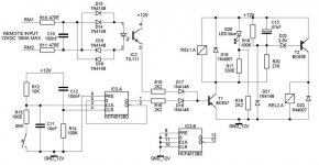
Build this little bugger about a year ago
notes
- relais 1 = mains on
- relais 2 = shorting the currentlimit resistors
- SW1 & D20, i used this one, offcourse the blue one
- R18 is not needed, but it makes the diode to "glow", so you can see if your mains is connected and your 12V supply is on. You need to adjust R17 & R18 if u use a different LED
- You offcourse also need a 12V DC supply
- Dont look at the connections on the TIL111, the pinout is wrong ( not the schematic, just the pins )
- Delay is about 1 sec, adjustabel with R20
For the resistors, don't skip in the budget here, make sure you have about 10Wresistor / 100VA transformer.
Now, the reason why you use this, is already known, you can use a smaller value for the fuse for the main transformer, but try to adjust the resistor ( inrushcurrentresistor ) value to a level that your fuse is smaller then the VA value off the transformer, i use 1.25A for my 300VA transfo, sow if i short my secundairy side, the fuse blows. With the value that is recommended by the manufacturer ( 3A = 700VA ?, the fuse never blows, only the transfo gets hot ) This way your transfo wil never be distroyed.
If you need the rest off the schematic just ask it was to big do to it at once
Greetz Rudy
notes
- relais 1 = mains on
- relais 2 = shorting the currentlimit resistors
- SW1 & D20, i used this one, offcourse the blue one
- R18 is not needed, but it makes the diode to "glow", so you can see if your mains is connected and your 12V supply is on. You need to adjust R17 & R18 if u use a different LED
- You offcourse also need a 12V DC supply
- Dont look at the connections on the TIL111, the pinout is wrong ( not the schematic, just the pins )
- Delay is about 1 sec, adjustabel with R20
For the resistors, don't skip in the budget here, make sure you have about 10Wresistor / 100VA transformer.
Now, the reason why you use this, is already known, you can use a smaller value for the fuse for the main transformer, but try to adjust the resistor ( inrushcurrentresistor ) value to a level that your fuse is smaller then the VA value off the transformer, i use 1.25A for my 300VA transfo, sow if i short my secundairy side, the fuse blows. With the value that is recommended by the manufacturer ( 3A
= 700VA ?, the fuse never blows, only the transfo gets hot ) This way your transfo wil never be distroyed. If you need the rest off the schematic just ask it was to big do to it at once
Greetz Rudy
Attachments
the reason why it is so big is simply the use off a button, not a switch, and the use off the opto and the bridge for that one.
For the SCR's, i just don't like them, i don't put a generator in my amp in combination with an antenna ( transformer ). Relais don't last as lang as the scr, but your telling me you or gonna use your amp for 40years ? I don't think so, and then so what, just replace it after 20 years of so, its max 5buks, sjeez.
And if you are not experienced witch SCR's, meening no RC and proper driving it, hell, it won't last a week. Just a switch and a SCR is a very BAD solution imo. But the same has to be told about the relais, if you use a RC circuit on the relais contacts you won't need to be worried for a few decades.
Greetz Rudy
- Status
- This old topic is closed. If you want to reopen this topic, contact a moderator using the "Report Post" button.
- Home
- Amplifiers
- Solid State
- About my amps mains connections