Merry Christmas.
L.C. has a very special way to design his schematics and it does not always help to understand them.
But do not ask-him to change, i suppose it is part of his original way to feel electronic, and part of his talent, looking from a different angle, to get innovative ideas.
L.C. has a very special way to design his schematics and it does not always help to understand them.
But do not ask-him to change, i suppose it is part of his original way to feel electronic, and part of his talent, looking from a different angle, to get innovative ideas.
Yes, Hugh, you're perfectly right.However, hasn't been Bryston for using this approach for many decades?
I'm very impressed by your electronic culture (Not the first time
")
On the Bryston's schematics i'v found, they use a BJT to drive the output devices. Not so elegant because the Base -> emitter current. Did they use FET to drive the power transistors in one of their amp ?
That was new for me. (But i'm so far to know everything ;-)
Well, my thought about this architecture (the parts in my schematic) was:
As that can be adapted to BJTs as well as FETs output devices, we can imagine one unique board with all the previous stages, and the choice between two boards for the power units: one with BJT, an other with Lateral MOSFETs. An unique occasion to see if any difference in the way they sound ?
What do-you think ?
Last edited:
Bonjour Christophe,
Thank you for your reply.
I have carefully listened to this configuration - not measured rather, but critically listened only - and found an impression of harshness. You could expect this however since any distortion of mixed npn/pnp on each side would add additional on each half cycle, which in turn shows odd harmonics.
OTOH if you adopt npn and pnp asymmetrical for the outputs, viz the usually approach for most amps, you have undifferentiation transconductance, which indicate pushes towards to even distortions, most H2.
You have to choose whether you prefer very low distortion of H3/H5 or highish distortion of H2/H4. That depends which presentation you prefer look like, and you might even ask if the very odd harmonics are audible regardless the very vanishingly THD.
Your choose your poison.......
Ciao,
Hugh
Pink LEDs?????
No, they Infra Red Led. The package is a little bit pink.
Marc
That's great.
Please include your capacitor dimensions as I am currently trying to find parts.
May be if there is a real interest i will write i bom with references.
Marc
Bonjour Christophe,
Thank you for your reply.
I have carefully listened to this configuration - not measured rather, but critically listened only - and found an impression of harshness. You could expect this however since any distortion of mixed npn/pnp on each side would add additional on each half cycle, which in turn shows odd harmonics.
OTOH if you adopt npn and pnp asymmetrical for the outputs, viz the usually approach for most amps, you have undifferentiation transconductance, which indicate pushes towards to even distortions, most H2.
You have to choose whether you prefer very low distortion of H3/H5 or highish distortion of H2/H4. That depends which presentation you prefer look like, and you might even ask if the very odd harmonics are audible regardless the very vanishingly THD.
Your choose your poison.......
Ciao,
Hugh
Bonjour Hugh

Welcome back to DIY company, wish you great time and lots of new amp designs.

As we all know distortion profile changes its higer harmonics amplitude structure due to many factors, one of them is bias current of the output transistors/drivers. To find optimal setting, sweet spot, one doesn't need sophisticated analysing equipment, can in most cases also quite firmly rely to sound signature of presented material.
BIGBT is new only in using mosfet as driver as told by me many times, and that I see as advantage compared to BJT driver. Proper gain matching and biasing makes this triple a wining solution for an output stage.
Now we have ideal case of Idefixes building new TSSA BIGBT HP and he could tell us than his impressions comparing to other amps he owns.
We here found SSA BIGBT HP sound signature to be very cultivated, musical and full of details, compared to other factory made beasts.
Kind regards to Hugh and all

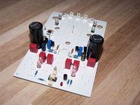
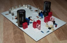
So here are start step, i soldered parts LC indicate me. These parts form the 3 CCS.
Hi Marc
According to red circles marked on TSSA BIGBT HP sch make following steps:
- connect +OUT pin to GND pin
- rotate VR2, VR3 to max resistance
- connect power supply +/-50 V and GND to proper PCB pins
- turn VR2, VR3 in a way that you measure 25 V voltage drop on R12, R21
- connect 9 V battery to J3-1, J3-2 and set value of R26 to get 37,5 V voltage drop on R4, R6
- check voltage drop on C6, C7, have to be app. 2 V each
- check voltage drop on VR1, VR4 TL431, it should be 2,5 V in both cases
- check voltage drop between pin 3,4 of TLP627, it should be around 0,2 V
- all five LEDs should lit too
By executing this procedure you have settled current sources/sinks to proper values.
Hi LC,
Connections as you indicate are not yet made. They are easy as i just have to plug fuse in socket and made a cable jumper between out facton pin and gnd faston pin.
For TLP627 supply i have on my soft-start/ speaker protection board a 0-12Vdc extra out-put that i can use just by cable connecting.
I am on wrinting a new topic on TSSA BIGBT HP building we will continue further step overthere if you are aware for more clarity.
Marc
I prefer as less distortion as possible.You have to choose whether you prefer very low distortion of H3/H5 or highish distortion of H2/H4. Your choose your poison.....
I don't see where this configuration can add distortion, comparing to a pure NPN or pure PNP half amplifier: i believe the only effect will be to slightly reduce even distortion because the symmetry of the two half waves.
If NPN and PNP are different in distortion, they will add their own by a x 0.5 factor because they are paralleled. So it is supposed to reduce by 2 odd distortions in the same time.
The FET driver add some more advantages, i think.
First FETS are usually faster and will not add a pole too close to the NPN/PNP's one.
Second, it is more linear, (less odd distortion). It do not require polarization (only for fixing the quiescent current) and react more like a pure resistance, while NPN/PNP behave more like a Voltage source. And they are hight impedance: better isolation with the previous stages.
Third, the parasitic gate/source capacitance will not have all its inconvenience here, because the current across-it will be added to the signal at the base of one of the output device.
Fourth, if we use Lateral MOSFETS, baecuse their negative temp factor, they will (partially ?) compensate the temp factor of the NPN/PNP device.
Comparing to the Bryston amps, we are in a totally different world, because Current feedback. And here, the huge open loop bandwidth of the amp will reduce high order distortions as well as prevent from TIM. I think the musical signature will be totally different.
With CFB, global loop is a bonus, with no negative effects.
Last, if you agree that there is not so much disparities between NPN and PNP devices, once paired, so not so much difference with a conventional schematic with BJT devices, the advantages of this configuration will be obvious with FETS where gate/source capacitances are impossible to match.
L.C., i would like to have you sentiment about this idea (May-be it was yet in your head ?) to have two different output stages technology (BJT, FETs) with the same previous stages ?
Last, if you agree that there is not so much disparities between NPN and PNP devices, once paired, so not so much difference with a conventional schematic with BJT devices, the advantages of this configuration will be obvious with FETS where gate/source capacitances are impossible to match.
That' my case ; all bjt and fet are matched
Marc
Hi LC,
Connections as you indicate are not yet made. They are easy as i just have to plug fuse in socket and made a cable jumper between out facton pin and gnd faston pin.
For TLP627 supply i have on my soft-start/ speaker protection board a 0-12Vdc extra out-put that i can use just by cable connecting.
OK, yes all necessary connections have to be made to power up the LEDs and CCSs.
Can you please postpone new thread until we make the amp running as planed. When it will work properly, than yes start a thread to inform the others about your amp.I am on wrinting a new topic on TSSA BIGBT HP building we will continue further step overthere if you are aware for more clarity.
Marc
OK, yes all necessary connections have to be made to power up the LEDs and CCSs.
Can you please postpone new thread until we make the amp running as planed. When it will work properly, than yes start a thread to inform the others about your amp.
Ok i just summing informations (advices, schema, apprairing process..)by side in word format.
Marc
- Home
- Amplifiers
- Solid State
- TSSA - The Simplest Symmetrical Amplifier