Hm...interesting question
hehe you know something I shoulda known too, please talk
Meaning that amp? I got one still going strong. Using it for when everything else is under planning or cruel operations.
Not that one but this one, and my moded one.
dado
Attachments
Yes, and transmission lines present a good acoustical charge to dump the speaker at the resonance too.A transmission line of cause does also not need a high damping factor because it has a quite flat impedance curve in the bass.
Transmission lines and 1/4 waves are probably the best enclosures for Bass, although not always possible (QTS of the boomer) and sooo complicated to build.
On my side, I do not care too much about the influence of the serial impedance of the amp on the response curve, as my speakers are all compensated (motional and self) to present a near flat impedance on all the bandwith (6ohms +- 1 ohms).
So the influence of the damping factor of the amp is mainly on pulse response.
Having a flat impedance helps the amp, too, because it do not have to deal with disparate (word is correct ?) Voltage/Current ratios, depending on frequencies.
I will never understand why manufacturers do not care this aspect.
Not that one but this one, and my moded one.
dado
Which one he published last, mine or yours with the Mosfet Vas?
PRAT is everything
I don't know what kind of music you guys listen to, but for me Jazz is the most revealing, true "acid test", since PRAT (Pace Rhythm And Timing) is everything at Jazz. Live Jazz performances daily in summer time offers major experiences, sound absorptions, tasting and learning how live instruments and Jazz band should sound. System must be capable to reproduce near live experience and that happens only when PRAT is OK. Musicians come together playing the same tune, they're tuned together, if not, complex Jazz takes sounds like tune's falling apart, musicians not playing in the same composition. To me Y axis correlations (phase, time, frequency) are the most important ones, amplitude related distortions are much more tolerable.
I could hear Jazz band from 1 km distance and I would immediately know it is live band playing: transients (speed), phase synergy, PRAT tells me that.
Which one he published last, mine or yours with the Mosfet Vas?
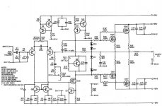
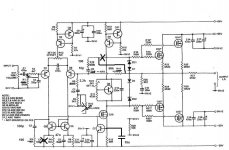
It was published in EW-WW 1984 July to August, later he changed it a bit, but I do not have that magazine(I think it was 1989.)
I don't know yours, I see it first time.
dado
Which one he published last, mine or yours with the Mosfet Vas?
Salas, the later JLH with mosfet vas has transformed into a Fetzilla

The idea of matching P and N channels (by differing the gate stopper resistance) are also still adopted in Fetzilla, not in your older version of JLH (I think mosfet was still new for him then). Even in Dadod version of JLH, JLH used a series of 2 resistors for gate stopper. In later model JLH used only one resistor, and that is lower value than yours (330R for N, 270R for P. Yours are 680R for both). Go figure
.. look like squaring the circle, because gate capacitance are varicaps, depending on the gate voltage in a different way between the N-channel and P channel.The idea of matching P and N channels (by differing the gate stopper resistance) ...
Paralleling a cap to reduce the C delta, playing with gate stopper to equalize the low pass filter (created with the capacitance holes) between the P & N devices ?
Never found a good enough response.
So, i believe the only thing we can really do is to allow the driver to never run out of current in the worse situation with the gate resistance little enough for keeping the desired bandwidth in the worse situation too and forget about matching... Am-i wrong ?
What are your experiences about this problem ?
So, i believe the only thing we can really do is to allow the driver to never run out of current in the worse situation with the gate resistance little enough for keeping the desired bandwidth in the worse situation too and forget about matching... Am-i wrong ?
That's what I have opted to believe.
The gate stopper, the source balancing resistor, the compensation capacitors (including intrinsic gate capacitance), all have similar effects to my ears, but with different severity, with capacitor being the worst (a lot worse).
I think one should not forget that the prime feature of the T/SSA is the possibility to use minimal compensation (for whatever target bandwidth). Even a cap as big as 47pF between base and emitter, like in Sonya's TSSA, is not my cup of tea. Cap across FB resistor is fine.
But of course, oscillation is not better than the existence of a small cap. But if we can get away with minimal capacitance, then that’s the way to go.
Capacitor between gate and drain/source to match the P and N imo is a strange decision. Gate capacitance is already the main issue with mosfet amps, now why add more? We can never match P to N anyway!
I have used this matching approach with Crescendo and Russel Breden’s amp, just to see if it improve anything, but I couldn’t perceive improvement so I went with simple common sense.
Gate stopper has similar effect imo. We want as minimal as possible, but often, design dictates that a small amount is better than nothing. But 680R is too big imo. May be 470R is the maximum (otherwise change the design). The best value might be achieved from measurement or listening, but the difference won’t be too critical imo, so I have never wanted to waste time on finding the best value (mostly because I already have stock resistors for this purpose), nor to use different value between N and P channel gates.
First of all.. The capacitance is placed between Collector and Base.
Second, they replaced an unlinear capacitor between drain and gate in the Renesas mosfet which KSC3503 and KSA1381 replaced....
If you say you don't want capacitors it plain rubish!!!!!!! You will proberly try to replace parts until it is stable. But then the parts you insert is with an unlinear capacitance...
Physics law give you capacitance every where you have to trace or metal surfaces with a given distance between them. The smaller this distance => larger capacitance. Larger surface area => larger capacitance..
Sorry, but you guys that want an amp without capacitors for compensation is completely of track....
I hope not that you are technicians or engineers!??? if so i think you have wasted time on your education...
Sorry for being that hard!
Sorry, but you guys that want an amp without capacitors for compensation is completely of track....
I believe that you do know the audible effect of the capacitors
But like I said, design issues usually dictate the use of the capacitor. It is then a challenge how to make the amp stable without too much capacitance. The CFB is already one solution towards that.
Of course, amp quality cannot be seen from the amount of capacitance or compensation. Only when the topology is similar, it starts to make sense to compare the amount of compensation used.
Second, they replaced an unlinear capacitor between drain and gate in the Renesas mosfet which KSC3503 and KSA1381 replaced....
With the availability of computer aided design tools, designs should become easier, as long as designers know what they want to achieve. Simply throw away new devices into old circuits, and if we're lucky, we may get a wonderful amplifier. All amateurs can do this. Finding the sweet spot, that's what the pros should know better.
I would like to try low capacitance mosfet such as the ZVN/ZVP stuffs with that topology you use. May be you have tried (well, you should) but couldn't find results up to your standard. For me, building and comparing by ears is the last effort. Your decision with BJT and 47pF cap might be the best solution for the topology (at least for now), how can I know without building and comparing?
But anyway, I found that gate driving is the determinant factor for good sounding mosfet amps. And contrary to Joachim beliefs that we can get away with less with drain output amplifier, I found that drain output amplifiers also in the same trouble. Currently, the topology used by Nico and Shaan (SSA, Source output) is the best for LatFet for that matter. For drain output, try driving the gate with/from emitter of a TO-92 CFP.
I strongly believe that the best T/SSA in the next few years is none of the circuits available today on this thread
Is-it not the same thing ? Running out of current doesn't means to have too much impedance in the source ? I presume you mean cascodes in crescendo does not fulfill the requirement ? I 100% agree.Enough current is not enough. Low impedance drive would do it.
Not a bad idea to experiment on the major source of non linearity in an amp using power mosfets output devices. The driver stage has to be a near 0 Ohm output impedance for we can forget the C variation of the power gates and high speed. Not easy.
Means a more complex driver stage than a simple emitter follower, i think. A cascode emitter follower (we need bandwidth here) ? More gain with local feedback ? How much do we need to overkill ?
.
Is-it not the same thing ? Running out of current doesn't means to have too much impedance in the source ? I presume you mean cascodes in crescendo does not fulfill the requirement ? I 100% agree.
Not a bad idea to experiment on the major source of non linearity in an amp using power mosfets output devices. The driver stage has to be a near 0 Ohm output impedance for we can forget the C variation of the power gates and high speed. Not easy.
Means a more complex driver stage than a simple emitter follower, i think. A cascode emitter follower (we need bandwidth here) ? More gain with local feedback ? How much do we need to overkill ?
IMO it is about a current source vs a voltage source, current sources (ideally) are high impedance and are not capable (mostly) to charge a capacitor in (near) 'zero' time (or there about). Voltage sources (ideally) have a 'zero' impedance, and thus are capable of charging capacitors in 'no time' at all.
Cascoded Darlington, if we can afford voltage drop ?
Of course, we were talking about voltage source with this "no current limitation".IMO it is about a current source vs a voltage source.
Last edited:
Listen very carefuly I will tell this only once. 
The best SSA real world implementation so far is SSA BIGBT HP with CCS without any tiniest doubt. After VAS there's the most suitable source follower mosfet driver for the job, with lowest possible input/reverse capacitance influence, one can get on the market. Tested throughout and confirmed by listenting experiences.
Jay, before you write unconfirmed assumptions, it would be nice from you first to follow complete procedure: R&D, simulation, production, testing, listening, results. Standing still at sim results means nothing without practical realization of the circuit, it is like talking to the wind. So far you didn't show us anything more than just the letters on the screen.
- Home
- Amplifiers
- Solid State
- TSSA - The Simplest Symmetrical Amplifier