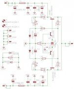
New tryout on pcb layout, i swap big caps out of board so the pcb mesure 100x56mm
Is this version OK to build?I'm asking cause I've the trannies
Attachments
Is this version OK to build?I'm asking cause I've the trannies
No beacause i swap on TSSA BIGBT HP
Marc
Is this version OK to build?I'm asking cause I've the trannies
It's OK to build and test, especially in P2P first, to evaluate sound acceptability with your speakers. The mosfet outputs version was checked many times, so you can swap from bipolar to mosfets if the speakers are too low Z - demanding.
")
No beacause i swap on TSSA BIGBT HP
Marc
... something stopped you on the way

... something stopped you on the way
The sun.....and garden work.... So i need to mesure BC560/550 and KSA/KSC. I want to etch a new pair of board since Irf pinpad are not sufficient nice for me. Eagle introduce larger hole when you switch form screen to printer. So i modify library in consequence. When all that's achieved i need the implementation/test step procedure....
Marc
When all that's achieved i need the implementation/test step procedure....
Marc
Will do that
The mosfet outputs version was checked many times, so you can swap from bipolar to mosfets if the speakers are too low Z - demanding.
Hi Busy Cat
I am a little lost...
please show schem of the the simplest version with mosfets OPT
thank you in advance
Hi All.
I have been very quiet about the TSSA and i have not been responding on the last order of KSA1381ESTU and KSC3503ESTU.
I am waiting on a plain in Helsinki, so i have some time to write you all.
The reason for me not responding is that there is serious issue with the TSSA circuit. We have tried to solve it, and Andrej has come with an solution that i need to try.
But basically what happens is that when we overdrive it with a load, DC levels on the front-end starts to shift and the transistor turns off and generates crossover distortion. The front-end will slowly regenerate from this fault over several seconds.
For this reason i am not going to offer the boards in its present state - They are not up to my standards!
I have attached the measurements.
I will offer an pure 2 stage amp. If the circuit Andrej has drawn will solve the problem it will be an real TSSA 2 stage, if not it will be a 2 stage amp with SSA or diamond buffer input.
No doubt about the sound quality of the 2 stage - It is good, but at the same time don't expect more than 40 - 50Watt @ 8R from it. In most cases this will be enough.
The TSSA modified to an SSA does not have this problem. But it then has the drawbacks of the SSA with pour DC stability.
The diamond buffer is very stable in terms DC stability.
- Sorry. But i thought it was more in place to be honest with your fellows.
Attachments
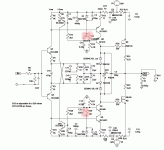
Hi to all 
Here's Sonny's TSSA Basic V1.5.
Also I added Esperado's Crescendo SSA modification with very similar values of DC decoupled feedback bridge and he never reported similar crossover distortions issue.
The difference to SSA is that SSA has DC coupled fb with low DC load impedance (200 Ohm - two 100 Ohm fb gnd resistors), at TSSA the DC load impedance are only two 1 k feedback resistors in series, so 2 k all together. CCS in SSA inject 10 mA into fb bridge, at TSSA only 1,8 mA.
The problem Sonny reported persist only with output load connected, so there's some current leak out/in from bridge's DC potential and as this serves the bias to the input pair and to whole two stages of the TSSA, so it normally should be stable.
I also attached my proposal to hold DC potential, it could also be some small resistor value ie. 100 Ohm resister as well. It should be tested though.
Attachments
Last edited:
Hi to all
Here's Sonny's TSSA Basic V1.5.
Also I added Esperado's Crescendo SSA modification with very similar values of DC decoupled feedback bridge and he never reported similar crossover distortions issue.
The difference to SSA is that SSA has DC coupled fb with low DC load impedance (200 Ohm - two 100 Ohm fb gnd resistors), at TSSA the DC load impedance are only two 1 k feedback resistors in series, so 2 k all together. CCS in SSA inject 10 mA into fb bridge, at TSSA only 1,8 mA.
The problem Sonny reported persist only with output load connected, so there's some current leak out/in from bridge's DC potential and as this serves the bias to the input pair and to whole two stages of the TSSA, so it normally should be stable.
I also attached my proposal to hold DC potential, it could also be some small resistor value ie. 100 Ohm resister as well. It should be tested though.
I will get back to this on friday when i am back.
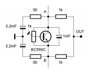
Ok, after some thinking a simulation where i could recreate the crossover.
I have an reason for the issue and a solution.
Reason:
When driving the input to 2Vpp the current through the feedback network is 20mApp in each feedback network. As long as the output stage can give the input voltage swing multiplied with gain very little current from the feedback network will flow into the feedback network.
But in the case where the output stage reaches its limit the current will start to flow into the input pair and reverse bias the be diode.
To solve it:
We need to raise the input pairs bias current to above the level of current that flows in the feedback network. => 10mA.
Problem that rises from deep:
If we raise the bias current in the input stage we need to lower the collector resistor by the same factor that the current is raised with. And this leads to an openloop gain that is the same factor lower.
Solution:
The soulution (Did i misspell something here???) is to insert a bias current of 9mA across the collector resistor. Now we can raise the collector resistor to 10K which is ~5x more open loop gain...
Now we only need to make a precise balanced non drifting current mirror!
I think this must be the contest of today!
I have attached a simplified schematic and simplified spice model of it.
It took me 3 pints of Finnish beer which is in average not stronger than a danish light beer to get to this solution.
My favorite beer is Midgård from Dansk Mjød A/S
The label says: Midgårds beer is a Gods beer from the Danish mead (Do you now this beer Michael???)

The only beer for Gods music through the DIY gear made for gods!!!!!
The FFT that is attached shows the potential of this simplified TSSA V1.6
Comments to the simplified:
It would be a good idea to add the CFP to the input pair as Gerhard has suggested. The FET cascode will be modulated a lot. Even to the point where the vgs voltage gets down to zero shorting the input pair.
Have a look and in the mean time i will change the schematic for the TSSA V1.5
I have an reason for the issue and a solution.
Reason:
When driving the input to 2Vpp the current through the feedback network is 20mApp in each feedback network. As long as the output stage can give the input voltage swing multiplied with gain very little current from the feedback network will flow into the feedback network.
But in the case where the output stage reaches its limit the current will start to flow into the input pair and reverse bias the be diode.
To solve it:
We need to raise the input pairs bias current to above the level of current that flows in the feedback network. => 10mA.
Problem that rises from deep:
If we raise the bias current in the input stage we need to lower the collector resistor by the same factor that the current is raised with. And this leads to an openloop gain that is the same factor lower.
Solution:
The soulution (Did i misspell something here???) is to insert a bias current of 9mA across the collector resistor. Now we can raise the collector resistor to 10K which is ~5x more open loop gain...
Now we only need to make a precise balanced non drifting current mirror!
I think this must be the contest of today!
I have attached a simplified schematic and simplified spice model of it.
It took me 3 pints of Finnish beer which is in average not stronger than a danish light beer to get to this solution.
An externally hosted image should be here but it was not working when we last tested it.
My favorite beer is Midgård from Dansk Mjød A/S
The label says: Midgårds beer is a Gods beer from the Danish mead (Do you now this beer Michael???)
The only beer for Gods music through the DIY gear made for gods!!!!!
The FFT that is attached shows the potential of this simplified TSSA V1.6
Comments to the simplified:
It would be a good idea to add the CFP to the input pair as Gerhard has suggested. The FET cascode will be modulated a lot. Even to the point where the vgs voltage gets down to zero shorting the input pair.
Have a look and in the mean time i will change the schematic for the TSSA V1.5
Attachments
- Home
- Amplifiers
- Solid State
- TSSA - The Simplest Symmetrical Amplifier