Yesterday evening i made a comparison of mosfet versus NJW1302G/3281G with MJF15030/15031 in darlington configuration with an emitter resistor of 0.22R
idle current is 1.8Amp.
In the simulation the THD for the exicons is 0.014% at 2.8Vp into 8R
for the darlington it is 0.004% at 2.8Vp into 8R
The thing is, they are easier to get, and cost 2/3 of the exicons.
At 1.8A and +/-32VDC we will dissipate 57Watt in each output device.
In comparison the exicons can handle 125Watt and the NJW's 200Watt.
With and heatsink of 0.4W/K the heatsink temperature will rise with 45.6K.
With 57Watt in the exicons it will rise to 102.6K leaving only 47Kelvin to the roomtemperature.
With the NJW you will have 35.625K leaving 68Kelvin to the room temperature.
I do not think it is safe to use the exicons or other devices rated lower than 200W for +/-32VDC supply voltage.
There is a lot talking against mosfets here.
Let me know what you think.
- Sonny
Is it not the same power dissipation at the same bias/rails for both types of devices, resulting in a same temperature increase. Using darlingtons would demand thermal compensation of some sort, laterals can handle without.

I will change the fets to J112 and J175.
They are easier to get and lower nV/SQ(Hz)
Good choice.
The input stage can be improved much, i do not think that it is just the synergy...
Yes, agree about input stage. Synergy, am I missing somehing here hehe
Fine. Then we need to lower the rails.
The layout will not be that different for both types.
So i am going to make two layouts.
TSSA with EXICONS and TSSA with NJW BJT's
What if leave +/-32V and lower the bias, it would be fine to have more output swing headroom here. Distortion profile wouldn't change dramatically by lowering bias to let's say 1,5 A?
This way the current through the input BJT will be the same and symmetrical regardless of bias current and offset adjustment. => Every amp will sound the same way.
What about cascoded inputs? Maybe in this case you wouldn't need extra CCS for bias/offset, as sound would stay pretty much the same regardless input biasing.
Attachments
I set up the input stage to have constant power. Basically it is Baxandall pairs cascoded with J-Fet´s, parallel symmetric so it can be called a cascoded band gap reference. The signal path is as short. It goes now through the J-Fets to the LatFets and the feedback is sensed by the Baxandall pairs.
I just wanted to say that there are better solutions then the lone bipolar pair. Even that version plus CCSs sounds great to begin with. I really like the basic idea of post 1.
I personally think that i can not hear better then 0,1% low order distortion so to make the circuit more complicated to get PPM distortion is not so attractive to me when it looses the simplicity.
You still change the working point of the transistor.
Even if the hFE of the transistor is relatively flat. it will start to fall at above 2 - 3mA. So if your current starts to get above 2 - 3 mA because of offset and bias adjustment the transistor is not that linear any more.
http://www.nxp.com/documents/data_sheet/BC859_BC860.pdf
Look on page 5.
So i would still use the separate bias and offset circuit. But adding the cascode to the front will raise the bandwidth of the input pair and lower distortion due to crossover.
I set up the input stage to have constant power. Basically it is Baxandall pairs cascoded with J-Fet´s, parallel symmetric so it can be called a cascoded band gap reference. The signal path is as short. It goes now through the J-Fets to the LatFets and the feedback is sensed by the Baxandall pairs.
WOW it sounds appealing, would love to see it if you can make a sketch.
I just wanted to say that there are better solutions then the lone bipolar pair.
Agree, we stay within two amp stages like it is now, only to convert each of them to max performance.

So i would still use the separate bias and offset circuit. But adding the cascode to the front will raise the bandwidth of the input pair and lower distortion due to crossover.
OK you got the point, also Gerhard with Baxandall pairs cascoded as inputs. We have to explore both options to choose best one for the input.
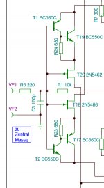
Here is the input stage, constant voltage and constant current = constant power .....
memdist = min?
- Home
- Amplifiers
- Solid State
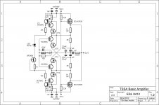
- TSSA - The Simplest Symmetrical Amplifier