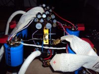
I build the super simple version of post one. It worked right away. I made some additions and changes. I run it on plus-minus 35V with 500 Ohm resistors instead of trimmers. I runs quite hot that way but i can stilll toutch the cooling profile so it must be around 55° Celsius.
I added a low pass filter at 3MHz -3dB. This amp is very fast and with the filter the square wave is clean. I have cap multipliers in the PSU. That way the amp is dead quiet on my 95dB sensitive speakers.
The sound is a bit lighter then with my power buffer ( see MPP ). By adjusting the gain in the preamp and using a warmer sounding cable i got it going. I have to listen more but the amp is very transparent.
Hi Joachim
 long time no "see"
 ")
Hey, first post worked right away, very nice to hear the news hehe, like that.

OK, what to do to make it more heavier, definitely something on bias and low spectrum linearization. Diodes 1N4148 forward voltage reach threshold potential of input Vbe quite fast, few mA of forward current is enough. But we want a little more current here to make diode potential more stable, independent of feedback current modulation. So solutions are two:
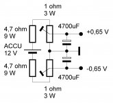
- using diodes with lower forward voltage characteristic than 1N4148 and feed them with more current to get to the right potential to bias input pair - brutal current force will make +0,65V and -0,65V potential much more stable
- logically more uF of elcos parallel to diodes would help to maintain stable DC potential too, also AC current transfer frequency characteristic would go down substantially
To resume, try to use Schottky diodes BAS70 or similar instead 1N4148, you will have to bias them with much more forward current to get just the right bias potential for the inputs. Secondly try to higher elcos to 4700uF each, bass response should improve. Also you can experiment to decouple diodes with film caps 1uF or 0,1uF.

The main aim with all this measures is to make +/-0,65 V DC potential as stable as possible. I am very curious what the results would be, regards Andrej
Sure, i just build it as is to study it. What do you think to replace the 1kOhm resistors with CCS´s ? Gives more open loop gain but stability has to be watched.
In a simple design as TSSA is, each and every part must tend to its theoretical maximum for the role in the design.
Yes CCSs would definitely be much better choice in this position than resistors, certainly.
Before CCS you can try quick&dirty test from schematic attached, just to be sure this is the right direction to go.
This simple circuit will completely eliminate feedback current influence. Sound check with this test bench will also tell you more.
Attachments
When Josie come home
So good
She´s the pride of the neighborhood
She´s the raw flame
The live wire
She prayes like a Roman
With her eyes on fire


According latest LC advises on empty space and trace length...
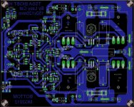
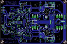
Nice progress Idefixes. As this is single layer PCB it's understandable that you're playing inside limited options. Wire jumpers sometimes are just not enough, space optimization in this kind of PCB depends only on designer's ingenuity. You're getting close to the limits, but still some more room for improvement.
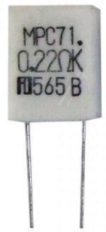
Also the output's emitter resistors should be different, MPC71, 0,22 ohm/5W, non-inductive should find place here. 10 ohm zobel resistor should be 2 W, much smaller than the present one.
TLP627 area is to crowded and too close to screw. Move BF245B + resistor to the other side and put blue LED in the middle position near the input. It's always nice to maintain symmetry from the sch to the PCB as well.
Input BJTs should be closer with pins since their flats will be glued together.
Orientation of the IR LEDs should maintain their serial position as on sch, no brainer when installing the parts and soldering.
I still see separated crowded building blocks from sch like islands, not spreading enough across the empty areas. When and if you will relax that blocks, tracks will automatically be shorter, individual parts will find more space around them. Yeah PITA job I know.
Attachments
Last edited:
Hi LC, Thanks one more time for new advices, i will rework. I would conserve PC length at 150mm as there is a 150x200 standart board. For MCP i must look on ebay as i couldn't find those brand on conventionnels store even internet stores. It's quite normal you can identify "crowded building blocks from sch like islands" as i split it into blocs. I will see if i been able to relax that blocs.
Could you give me the Voltage reating for 100µ, 1mF and 2.2mf to see if i could gain more space to adjust to real needing size?
Marc
Could you give me the Voltage reating for 100µ, 1mF and 2.2mf to see if i could gain more space to adjust to real needing size?
Marc
Hi LC, Thanks one more time for new advices, i will rework. I would conserve PC length at 150mm as there is a 150x200 standart board. For MCP i must look on ebay as i couldn't find those brand on conventionnels store even internet stores. It's quite normal you can identify "crowded building blocks from sch like islands" as i split it into blocs. I will see if i been able to relax that blocs.
Could you give me the Voltage reating for 100µ, 1mF and 2.2mf to see if i could gain more space to adjust to real needing size?
Marc
Printline
Printline - Speeding up your business
They are very professional and will save you for a lot of frustration.
Printline
Printline - Speeding up your business
They are very professional and will save you for a lot of frustration.
Sonnya thanks for advise, i will take a look even i things i don't like with professionnal pcb espeacialy with double layer and metalized holes are the difficulty of desoldering...With thin tracks or multiple pin compo it can become a pity. I don't doubt that i have to desolder on TSSA pcb board as it is a non "improved" design...
Marc
Hi LC, Thanks one more time for new advices, i will rework. I would conserve PC length at 150mm as there is a 150x200 standart board. For MCP i must look on ebay as i couldn't find those brand on conventionnels store even internet stores. It's quite normal you can identify "crowded building blocks from sch like islands" as i split it into blocs. I will see if i been able to relax that blocs.
Could you give me the Voltage reating for 100µ, 1mF and 2.2mf to see if i could gain more space to adjust to real needing size?
Marc
Marc, PCB design is a time dependant job as well, next day you see things that today seems impossible, specifics of designing. So make it in a slow process, take your time, at the end will be just perfect.
Parts specifics:
- 100 uF/16 V 3x
- 1000 uF/6,3 V (10 V) 1x
- 2200 uF/6,3 V (10 V) 2x
- supply decoupling elcos have to be 63 V for your +/-50 V version
- all elcos best of quality (Nichicon, Panasonic, Mundorf, ...)
- all resistors 2 W and down should be metal film
- MPC71 - on line order at very trustful Buerklin
Best regards Andrej
Then just order singlesided PCB.
Sonnya,
For single layer, i do it my own to house for quite long time, but it's more a pity to do it in artisanal mode in double layer....then printline is the solution.
Marc
Marc, PCB design is a time dependant job as well, next day you see things that today seems impossible, specifics of designing. So make it in a slow process, take your time, at the end will be just perfect.
Parts specifics:
- 100 uF/16 V 3x
- 1000 uF/6,3 V (10 V) 1x
- 2200 uF/6,3 V (10 V) 2x
- supply decoupling elcos have to be 63 V for your +/-50 V version
- all elcos best of quality (Nichicon, Panasonic, Mundorf, ...)
- all resistors 2 W and down should be metal film
- MPC71 - on line order at very trustful Buerklin
Best regards Andrej
Thanks LC.
For Elcos i like to use panasonic FC and NHG (2200µ 63V). For Smoothing cap i have United chemicon U32D in 22.000µ 63V 4 unit, may add 4 for to have 2x22.000µF 63V per rail per amp board.
Marc
Last edited:
Nice progress Idefixes. As this is single layer PCB it's understandable that you're playing inside limited options. Wire jumpers sometimes are just not enough, space optimization in this kind of PCB depends only on designer's ingenuity. You're getting close to the limits, but still some more room for improvement.
Also the output's emitter resistors should be different, MPC71, 0,22 ohm/5W, non-inductive should find place here. 10 ohm zobel resistor should be 2 W, much smaller than the present one.
TLP627 area is to crowded and too close to screw. Move BF245B + resistor to the other side and put blue LED in the middle position near the input. It's always nice to maintain symmetry from the sch to the PCB as well.
Input BJTs should be closer with pins since their flats will be glued together.
Orientation of the IR LEDs should maintain their serial position as on sch, no brainer when installing the parts and soldering.
I still see separated crowded building blocks from sch like islands, not spreading enough across the empty areas. When and if you will relax that blocks, tracks will automatically be shorter, individual parts will find more space around them. Yeah PITA job I know.
Hi LC, here's my interpretation from advices you give.
Attachments
Last edited:
Hi LC, here's my interpretation from advices you give.
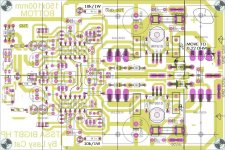
And here's my interpretation of your PCB.
Explanations:
- MUR460 are size as now
- power supply indication LEDs need 5 mA, 10 k/1 W resistor is enough
- move left part of PCB to 0,22 ohm to get equal distance from both MJL to IRF (IRF exactly in the middle)
- use PCB area over outputs to spread the parts more freely (power supply pin, fuse, 0,1 uF etc)
- align outputs pins to the same horizontal grid
- use horizontal middle symmetry line to get simmetry from lower and upper part of the pcb (2N5462 according to 2N5486 etc)
- TLP section rearanged as you can see
- align input BJTs, trimmers, etc (parts in the middle) to horizontal middle symmetry line
- use wire jumpers of the same lenght, so one can prepare them as the same part in quantites
- etc
OK, I think you've got an impression now.
Attachments
And here's my interpretation of your PCB.
Explanations:
- MUR460 are size as now
- power supply indication LEDs need 5 mA, 10 k/1 W resistor is enough
- move left part of PCB to 0,22 ohm to get equal distance from both MJL to IRF (IRF exactly in the middle)
- use PCB area over outputs to spread the parts more freely (power supply pin, fuse, 0,1 uF etc)
- align outputs pins to the same horizontal grid
- use horizontal middle symmetry line to get simmetry from lower and upper part of the pcb (2N5462 according to 2N5486 etc)
- TLP section rearanged as you can see
- align input BJTs, trimmers, etc (parts in the middle) to horizontal middle symmetry line
- use wire jumpers of the same lenght, so one can prepare them as the same part in quantites
- etc
OK, I think you've got an impression now.
That's good impression.....they make me progress.....when it commes to such détails it smell good (direct traduction of a french expression)....
Thanks for spending time on my work to propre evolving.
Marc
The blue led i have ( VAOL-3LSBY4 VCC Standard LED - Through Hole )needs 20mA / 3.5v so lowering from 50 to 3.5 at 20mA need R=(50-3.5)/0.02=2.325kOhm at P=(50-3.5)*0.2=0.93w so with 2 1W resitors in // i have 2w power dissipation range and can get close to the 2.325kOhm. With resistor value between 2kOhm - 2.6kOhm i think i be in "fonctionnal" range value no?
Marc
Marc
- Home
- Amplifiers
- Solid State
- TSSA - The Simplest Symmetrical Amplifier