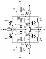
Logical evolution: TSSA with VAS.
One benefit this amp has, the 1N4148 bias potential diodes thermally compensates input BJT-s Vbe tempco, thus stabilize VAS bias current.
It is a lot better. But i would recommend a cap across bias resistor.
Hi sonnya
Yes and also input cap, some decoupling caps etc. Intention of this sch is to show basic principle more clearly, it is not final product sch.
Did you test TSSA first post sch yet? This feedback bridge doesn't have any injecting current, which imediately brings two benefits, thermal stability plus no modulation of injecting current, simply because it isn't present.

Why No DC Servo?
I think I will prefer the bipolar if the distortion is close. But how close?
I'm curious why DC servo is not discussed with SSA circuits. It is hard to get a low THD without compensating other factors such as the DC offset (at least from simulation).
I will be building this TSSA but cannot yet decide on which circuit to build. Zero DC --> terrible THD. Good THD --> terrible DC.
I don't know what is the worse acceptable DC, 0.2 volt may be? But I think with such a simple circuit highish THD is okay, 0.3% may be?
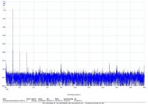
I have tried a -0.2V offset with 0.02% THD (1kHz, 2V input sinewave, 2N5401/5551, tho low noise TR performs better). May be I need to aim for 0.1V?
Might have to try this one. See how the bjt compares to jfet.
I think I will prefer the bipolar if the distortion is close. But how close?
I'm curious why DC servo is not discussed with SSA circuits. It is hard to get a low THD without compensating other factors such as the DC offset (at least from simulation).
I will be building this TSSA but cannot yet decide on which circuit to build. Zero DC --> terrible THD. Good THD --> terrible DC.
I don't know what is the worse acceptable DC, 0.2 volt may be? But I think with such a simple circuit highish THD is okay, 0.3% may be?
I have tried a -0.2V offset with 0.02% THD (1kHz, 2V input sinewave, 2N5401/5551, tho low noise TR performs better). May be I need to aim for 0.1V?
I'm curious why DC servo is not discussed with SSA circuits. It is hard to get a low THD without compensating other factors such as the DC offset (at least from simulation).
DC servo circuit cannot influence the distortion profile since it has the bandwith of influence of a few Hz or even less. Why we didn't put any effort on DC servo yet? Simply because there's no need, since the output DC fluctuations are within +/-50mV, of course if the input pair is thermally coupled. This DC offset at power amplifier's output terminals is none of practical importance, it is more cosmetic to have 0,5 mV here. For musical sources and preamps I agree, this value has to be below 1 mv.

Might have to try this one. See how the bjt compares to jfet.
Hi buzzforb
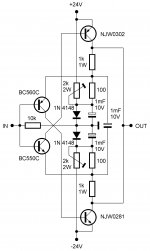
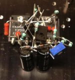
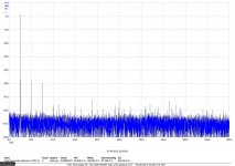
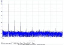
TSSA schematic from post #1, built by sonnya, all together four transistors only and as you can see from the pics very promising results.

Attachments
Member
Joined 2009
Paid Member
Logical evolution: TSSA with VAS.
no additional VAS please - the idea is simplest possible. To heck with THD, if it sounds good it is good


Member
Joined 2009
Paid Member
I love it, such a simple pcb. Some thoughts...
a) make the pcb longer and cover the power devices, then screw through the pcb, through the power device into the heatsink. You can eliminate the separate pcb mounting holes.
b) are you sure you can get 2W rated trimmers of that size ? you may need a power resistor in parallel with a lower wattage trimmer
c) leave a little space between the caps
d) move the resistors a bit further away from the power device leads which will tend to want a fair bit of solder around them
IF I understand correctly, the extra cap helps ensure balance between the two feedback loops, which will minimize even order distortion. I don't think it's a big issue to leave it out.
Last edited:
I love it, such a simple pcb. Some thoughts...
a) make the pcb longer and cover the power devices, then screw through the pcb, through the power device into the heatsink. You can eliminate the separate pcb mounting holes.
b) are you sure you can get 2W rated trimmers of that size ? you may need a power resistor in parallel with a lower wattage trimmer
c) leave a little space between the caps
d) move the resistors a bit further away from the power device leads which will tend to want a fair bit of solder around them
IF I understand correctly, the extra cap helps ensure balance between the two feedback loops, which will minimize even order distortion. I don't think it's a big issue to leave it out.
Who wants to minimize even order distortion
Question. If paralleling a resistor with pot, you want the power resistor to be smaller than pot so that it takes the heat, correctno additional VAS please - the idea is simplest possible. To heck with THD, if it sounds good it is good
Why not?

I could easily do TSSA BIGBT HP since it is much simpler than SSA and potentially even better performer.
Why not?
I could easily do TSSA BIGBT HP since it is much simpler than SSA and potentially even better performer.
do it, doit, do it....

Marc
Why not?
I could easily do TSSA BIGBT HP since it is much simpler than SSA and potentially even better performer.


- Home
- Amplifiers
- Solid State
- TSSA - The Simplest Symmetrical Amplifier