I could be from, since i have some 2SJ162/2SK1058 ond hand. BC550/BC560 could be use insted of bc850/560 seems like to be the smd brother of previous on. I have 300va 2x25vac trafo and some 22.000%f/40v screw caps. This board fit perfect for diy use : single layer => home etching....
Marc
Yes yes yes but first we have to finish TSSA BIGBT HP Marc.

Than and only than ... You see, it will be a very productive autumn-winter season, the man with the beard will carry a lot of gifts.

Yes yes yes but first we have to finish TSSA BIGBT HP Marc.
Than and only than ... You see, it will be a very productive autumn-winter season, the man with the beard will carry a lot of gifts.
Yes and no....because i have some etching run to do for TSSA Bigbt hp project....I could etch them together....
Marc
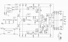
Schematic of TSSA SITO Audio just to have it in a close range. Sonny got remarkable sound quality with his SMT populated PCB's and there's more people on the way to build this amp soon. A lot of transistors involved to do the job properly, something different for a DIY-er to try, not just one more of standard blameless designs.
Attachments
Yes and no....because i have some etching run to do for TSSA Bigbt hp project....I could etch them together....
Marc
Thats a nice optimization Marc, yes, than make them both. You'll be the first to check Alex PCB functionality, also comparison data between them (two, threee stages TSSA) we could get.

With TSSA the PSRR is not as good as many amps . . . .
I wonder if it would sound better with regulated PSU ?
Any thoughts on that ?
Good idea, oversized SMPS (current delivery capability) with HQ smoothing caps (Mundorf etc) added on its output can be perfect solution for this one. Similar like NuForce is been doing for a long time.

With TSSA the PSRR is not as good as many amps . . . .
I wonder if it would sound better with regulated PSU ?
Any thoughts on that ?
Hi Mikelm.
I have no or very little hum on this amp with 2x22mF supply.
Just have to be tested.
With TSSA the PSRR is not as good as many amps . . . .
I wonder if it would sound better with regulated PSU ?
Any thoughts on that ?
Yes, the fragile part (and the TSSA weakness) is the input stage (is hard to beat F5 noise floor). But a complex current source, RC filter and separated power supply will take care of that. I found that less regulated separated power supply is more important than well regulated non-separated power supply (Talking class-A here).
I was not really thinking about hum, ( although it's nice to have no hum ) rather the supply rails being modulated by the signal and in turn this modulation affecting the i/p stage - I think you have dealt with this as much as is possible with your design with cascoded i/p devices and very good CCS design but I suspect a regulated supply may add some benefit.
I am a little nervous of SMPS because I believe low noise is of most importance for Audio - but perhaps I just don't understand SMPS design !
I am a little nervous of SMPS because I believe low noise is of most importance for Audio - but perhaps I just don't understand SMPS design !
I found that less regulated separated power supply is more important than well regulated non-separated power supply (Talking class-A here).
It is normal in this thread that a single PSU is always intended to supply one channel only. Dual mono internal structure, when we speak about stereo amplifier, always.

Yes, the fragile part (and the TSSA weakness) is the input stage (is hard to beat F5 noise floor). But a complex current source, RC filter and separated power supply will take care of that. I found that less regulated separated power supply is more important than well regulated non-separated power supply (Talking class-A here).
Hi Jay,
Do you mean separated L & R channels ? If so I agree 100% with TSSA.
What I cannot see is a way to separate the supplies for the i/p & o/p stages in a 2 stage design such as this because the rail is used as a reference.
mike
I am a little nervous of SMPS because I believe low noise is of most importance for Audio - but perhaps I just don't understand SMPS design !
Good SMPS-s normally have very low noise floor. I suggested you to use SMPS because I know you're very experienced with PSU filters, so you can make SMPS's audio upgrade on its output. CLC plus decoupling would do the magic, just take oversized (output current capability) SMPS (two for both channels) which PWM operates around or over 500 kHz. It should be in its own metal case and you could install two of them separately in the case (below or at the front plate). Many possibilities with SMPS one could do.
Hi Jay,
Do you mean separated L & R channels ? If so I agree 100% with TSSA.
What I cannot see is a way to separate the supplies for the i/p & o/p stages in a 2 stage design such as this because the rail is used as a reference.
mike
That is correct Mike.
If we would separate the mosfet from the input stage. Then our reference will be floating, and also the signal and idle current.
Hi Jay,
Do you mean separated L & R channels ?
What I cannot see is a way to separate the supplies for the i/p & o/p stages in a 2 stage design such as this because the rail is used as a reference.
If we would separate the mosfet from the input stage. Then our reference will be floating, and also the signal and idle current.
Ooops, sorry I mixed up with my Goldmund amp. Nonetheless, I found it strange also.

I am a little nervous of SMPS because I believe low noise is of most importance for Audio - but perhaps I just don't understand SMPS design !
I'm also nervous with my 200kHz SMPS. IC based L296, CLC outputs.
SMPS (two for both channels) which PWM operates around or over 500 kHz.
If over 500kHz I will not be nervous!
Mike,
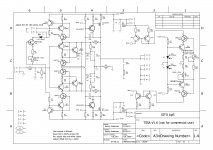
Since you like mosfet vas I went to dig up my old archives to show you a design that might be to your liking. This was a commercial design about 20 years old, Class A, 30 W, THD 0.08% 20Hz-250KHz.
It sounds very close to tube amps except its not so irritatingly sweet and doesnt kill the being live feeling tube amps do with rock music. Amp in the mould of Dartzeel. Theres an obvious mistake in schematics but it shouldnt be a problem for you. Its thermally stable and servo takes care of DC offsets. The same design was used for higher power upto 100 Watts.
Attachments
a commercial design about 20 years old
I would have named it the Audio-Labor Heiß.
I would have named it the Audio-Labor Heiß.
I think that was the manufacturer yes, german I take it. As can be seen the frontend is a text book copy of the design shown by JLH back in late 60s. This design is very clever indeed when it comes to the use of feedback.
Audiolabor Flink (but Class AB, only 4'' high and no heatsinks)
=> http://audiomarkt.de/_markt/uploaded/0897805847_2_g.jpg
=> http://audiomarkt.de/_markt/uploaded/0897805847_2_g.jpg
Many models used the same schematic, the differences was only in the outputstage. I guess the case was the heatsink there. I listened to a Stark, Class AB, roughly drew the schematic, this model has 2 mosfets in parralell as vas and three pairs of sankens. Sounded bloody marvelous if youre into chamber classical or light orchestra music. Which model was class A ??
BTW I see these old amps selling for major euros secondhand considering their age, 2000 euros for Stark pair.
BTW I see these old amps selling for major euros secondhand considering their age, 2000 euros for Stark pair.
- Home
- Amplifiers
- Solid State
- TSSA - The Simplest Symmetrical Amplifier