No comment or is every one on highend München ????Ok, here it is.
The PDF is interactive, so you can click on the parts.
http://sitosite.dk/amps/TSSA-01010512.pdf
http://sitosite.dk/amps/TSSA-01010512-pcb.pdf
True, so many good sounding systems on a display, Dan's Momentum impressed me the most (among others).

Sonnya, perfectly laid parts on double layer PCB, will look today and report. Have a nice day.

Ok noted will say when i right up and sure will post pcb pictures.
Marc
Today I measured and tested all functional parts of TSSA BIGBT HP schematic separately. Not a single issue detected.
Yes please post PCB images as soon as they'll be ready.

Regards, Andrej
18000hours at 85 degrees Celsius.
I dont know, but 85degr caps may be gone soon
might be wise to make room for 105 degr caps
besides, I dont find BHC caps very often
mostly Rifa, B&C(Philips), or Panasonic
but 85degr caps may be gone soon
You try to find large lytics that do 4500 hrs at 105C.
Various alternatives of 15000uF/63V caps in 40x50, 4-pin size.
Panasonic T-HA, 3000hrs/105C, is 12000hrs at 85C.
(e.g. a Panasonic T-UP in that size only does 3000 at 85C)
The BHC ALC10 would last 200K hrs at 50C or 400.000 at 40C !
Last edited:
Oh i forgot. The ESL is not an issue at <1KHz.
If you look at graph for capacitors with Z (impedance) on the Y axis and Frequency on the X axis the impedance is a combination of Xc+Xl(series inductance)+ESR. The curve as a form as a valley at low frequencies the Xc dominates. At the bottom it is the ESR value. When it starts rising again it is the Xl value.
If the load is switching at lets say 500KHz with an ripple of 2Amp peak peak most aluminium capacitors starts to heat up. Tantal capacitors has a much higher resonance frequency (bottom of the valley).
I have had a aluminium cap in a SSA amp exploding because of oscillations in the amp.
The best parts for bypassing is ceramics as there resonance frequency is 10 - 100 times higher.
Best choice for bypassing op amps and digital circuits (or just fast circuits in general) is X5R, X7R, NP0, C0G.
NP0 and C0G has similar parameters. X5R and X7R is for high capacitance values.
Y5V is a NO GO!!! tolerance is -80% to +20%!!!!!!!!!!!!!!
NP0 and C0G can outperform film capacitors in sizes of 10nF and down.
If is would choose a miller cap i would take something like MICA, polyprop, NP0/C0G and compare them for there audible performance. But it is most likely that the MICA and NP0/C0G will be the parts that make the amp stable as there resonance frequency is much higher.
There is no magic to it, just interpreted the datasheet. If a parameter is missing it is mostly not as good as it should be.
elna audio caps has Lifetime of below 2000hours at 85 degrees celcius. That is not good enough in a hot amp. Nor does they say anything about ESR or ESL value.
What is your favorite input transistor?
Have you tried various transistor for the input stage? How do you choose your transistor? I found that in TSSA this transistor matters a lot. Usually I still can use my standard 2N5401 for prototyping but here it is not possible at all. Yes, low noise transistors work better but I was surprised that the difference is so big. Attached is a simulated comparison between BC557C/547C and 2N5401/5551. Actually the 2N5401 doesn't work at all even with 0.1V input while BC557 can give THD of 0.002% at 60W output
Have you tried various transistor for the input stage? How do you choose your transistor? I found that in TSSA this transistor matters a lot. Usually I still can use my standard 2N5401 for prototyping but here it is not possible at all. Yes, low noise transistors work better but I was surprised that the difference is so big. Attached is a simulated comparison between BC557C/547C and 2N5401/5551. Actually the 2N5401 doesn't work at all even with 0.1V input while BC557 can give THD of 0.002% at 60W output
Attachments
Started to build the first version of the TSSA (the schematic in post #1).
I got an -2.5V on the output without any load. I was to tired to troubleshoot so Im going to finish it tonight. Has anyone done schematic #1 successfully? This thread is to long to follow... =)
Nice work guys
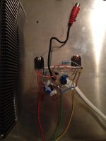
The amp:
I got an -2.5V on the output without any load. I was to tired to troubleshoot so Im going to finish it tonight. Has anyone done schematic #1 successfully? This thread is to long to follow... =)
Nice work guys
The amp:
Attachments
Hi McDaisy
Look to post #19, #20 Sonnya's work.
Also Gerhard did it.
Two trimmers serves to set the bias (output drain current) and output offset to zero. Sch is so simple that by rotating trimmers you should get linear readout change of these two values accordingly.
-2,5 V at the output simply means the offset is not finnaly set. Probably trimmer value should be changed if you reach the end position before zero output.
TSSA is a nice amp case of practicing electronics and gaining new experiences.
Regards, Andrej
Have you tried various transistor for the input stage? How do you choose your transistor? I found that in TSSA this transistor matters a lot. Usually I still can use my standard 2N5401 for prototyping but here it is not possible at all. Yes, low noise transistors work better but I was surprised that the difference is so big. Attached is a simulated comparison between BC557C/547C and 2N5401/5551. Actually the 2N5401 doesn't work at all even with 0.1V input while BC557 can give THD of 0.002% at 60W output
This is probably only the case in simulation or did you practically tested that 2N5401/5551 are not suitable.
Otherwise BC550/560 are very good for audio, best performance, low noise, at 1-10 mA bias (collector current).
This is probably only the case in simulation or did you practically tested that 2N5401/5551 are not suitable.
Otherwise BC550/560 are very good for audio, best performance, low noise, at 1-10 mA bias (collector current).
Only simulation (the fft is fine but distortion is not: it is not sinewave at the output). But with such a simulation result of course I don't want to use 2N5401.
I used BC550/560 actually. Even BC550 is not as good as BC557 (almost tho) in simulation. My original concern was: if transistor change can change the simulated result significantly, then it will be difficult to control the real result without real measurement and tweaking. No wonder someone got -2.5V at the output
TSSA is a nice amp case of practicing electronics and gaining new experiences.
Actually after giving up the 3-stage SSA, my intention with 2-stage SSA (or TSSA) was to learn and understand the circuit before working with 4-stage ones. But it seems 2-stage has some benefits, especially it can be used for high power version.
Anyhow, I don't understand the added complexity by the new current source etc. I saw only little improvement on simulation. I'm interested to build the sizklai ouput version but with IRF610/9610
 . Any circuit that sound good, yet? Otherwise I will just wait
 Hi McDaisy
Look to post #19, #20 Sonnya's work.
Also Gerhard did it.
Two trimmers serves to set the bias (output drain current) and output offset to zero. Sch is so simple that by rotating trimmers you should get linear readout change of these two values accordingly.
-2,5 V at the output simply means the offset is not finnaly set. Probably trimmer value should be changed if you reach the end position before zero output.
TSSA is a nice amp case of practicing electronics and gaining new experiences.
Regards, Andrej
Hi Lazy Cat!
Thanks for the quick reply... Ill check it out tonight. But I still think something is wrong. Its because Im using smps and it got hot really really quick so I disconnected it until I find the fault...
If this amp sound good Im going to build one with smps and double amps in each channel to make it balanced
My original concern was: if transistor change can change the simulated result significantly, then it will be difficult to control the real result without real measurement and tweaking. No wonder someone got -2.5V at the output
Not related to BCs but rather to N-P ch Vgs threshold difference.
Any circuit that sound good, yet? Otherwise I will just wait
It depends on stage's complexity-optimization level and DIY-er skils. Try TSSA Basic from post #1 and be surprised. All more complex versions discussed, like TSSA Basic 1.5, should perform much better.
Hi Lazy Cat!
Thanks for the quick reply... Ill check it out tonight. But I still think something is wrong. Its because Im using smps and it got hot really really quick so I disconnected it until I find the fault...
If this amp sound good Im going to build one with smps and double amps in each channel to make it balanced
Gerhard explained it in post:
I build the super simple version of post one. It worked right away. I made some additions and changes. I run it on plus-minus 35V with 500 Ohm resistors instead of trimmers. I runs quite hot that way but i can stilll toutch the cooling profile so it must be around 55° Celsius.
I added a low pass filter at 3MHz -3dB. This amp is very fast and with the filter the square wave is clean. I have cap multipliers in the PSU. That way the amp is dead quiet on my 95dB sensitive speakers.
The sound is a bit lighter then with my power buffer ( see MPP ). By adjusting the gain in the preamp and using a warmer sounding cable i got it going. I have to listen more but the amp is very transparent.
... and continued in following posts.
Thanks! Good reading. Ill come back with my result
As Gerard, Im doing this for studiyng purpose...
Try TSSA Basic from post #1 and be surprised.
How much WATT can you get at THD of no more than 0.1% with the vanilla circuit, and with the V1.5?
Last edited:
- Home
- Amplifiers
- Solid State
- TSSA - The Simplest Symmetrical Amplifier