
......waiting for modification to see if mistake are comimg from schematic or from library (frequently different pin assignation for same part). If schematic and library are right in eagle.....wiring should be right.
Marc
Marc
Yes, parts pinouts are the reason, nothing dramatical, only few corrections will folow. 😉
I saw very nice equipment in your web page, impressive builts indeed. TSSA should be like one of them, to fit in with quality. 😎
I saw very nice equipment in your web page, impressive builts indeed. TSSA should be like one of them, to fit in with quality. 😎
I saw very nice equipment in your web page, impressive builts indeed. TSSA should be like one of them, to fit in with quality. 😎
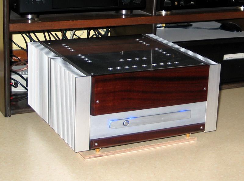
Thanks LC. I am on brainstorming about TSSA casing mix wood/alumium for sure, perhaps glossy lacker as i have painting equipment for (air compressor and car spray-gun)...
Marc
Last edited:
Yes, parts pinouts are the reason, nothing dramatical, only few corrections will folow. 😉
That's a real problem for parts purchasing. With some dealer you are not sure the brand you will have so possible pin layout differences. That's why i like to go to stores as mouser where when order onsemi you have onsemi in packet and for each part type,you can easy have online datasheets.
Marc
I am realy curious what listening test will show. Where on your favourite list TSSA will rank. Important and quality selective is also final assembly with wiring especially ground wires and grounding. 🙄
I am realy curious what listening test will show. Where on your favourite list TSSA will rank. Important and quality selective is also final assembly with wiring especially ground wires and grounding. 🙄
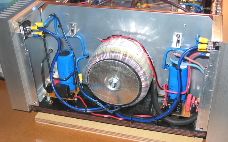
That's for sure and can be tricky. The design i have in mind stay on 2 mono blocs. Wiring must be as short as possible. I want to put the distance i can between power wiring and signal wiring. Also main AC wiring must be isolated from the rest as the trafo to. I think to install a steel plate to isolate trafo from rest of amp. For ground wiring i think i will drawn a little schematic a submit it to you.
Marc

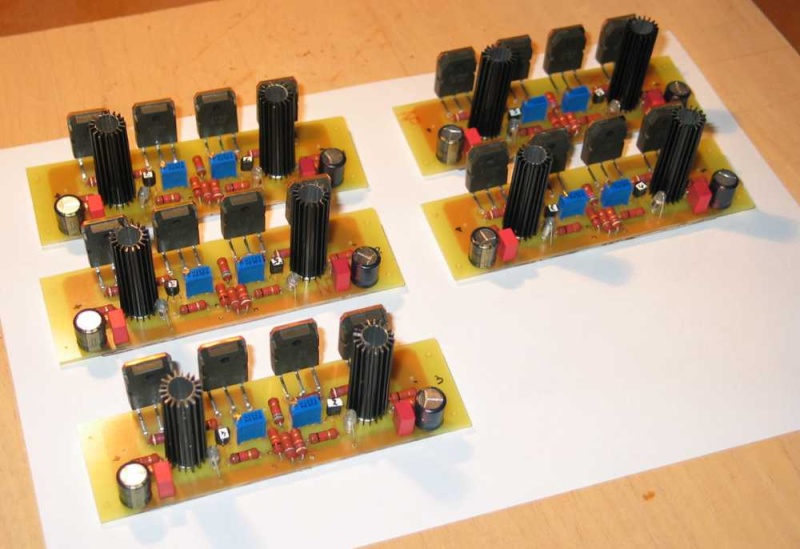
OK, here's my final check of PCB parts & wiring, also some component's position adjustments to enable wider tracks were done. Hopefully it would be managable, Marc what do you think? 🙂
Hi LC i will work on modification this evening. I was sure there was an issue with 2N. It's typicaly the part with pin layout depending manufacturer. The unit i ordered are normaly Fairchild and have different pin layout as onsemi. Is 2N5462 layout OK?
May there is an issue with 0r22 R13 new position see attachement.
Marc
Attachments

Last edited:
Yes, 2N5462 is OK. That in red circle is base track connection, it can be thiner no problem only mA flows. 0,22 ohm were actually moved to sides because of collector connections, tracks flows 10 Ap range current and now can be wider. 😉
What is your favourite amp from your collection, is it Pass Susy? 🙄
What is your favourite amp from your collection, is it Pass Susy? 🙄
Yes, 2N5462 is OK. That in red circle is base track connection, it can be thiner no problem only mA flows. 0,22 ohm were actually moved to sides because of collector connections, tracks flows 10 Ap range current and now can be wider. 😉
What is your favourite amp from your collection, is it Pass Susy? 🙄
Ok for advice.
Pass Suzy if you mean Upower is not complet at this time due the udge amount of component and their nature (per 6 matched IRP240 and 9240, 2SK389/2SJ109..) I have all this parts as far trafo, heatsink, smoothing cap - 8x33.0000 per channel)but need to purchase some more classical. The Upower you can see on my web page is my friends one. The first of a long series that was built as the guy (knowed Cheff de Gaar on diyaudio) is creator. UPower as the line stage UGS are borned from discussion between us. Me as just the beta tester. Great guy and great friend Cheff De Gaar.
I stop dyaudio building past feww year beacause of house buiding (coast much time and money). It 's only a few monthes i re-engage DIYaudio work.
I love all i built with a little preference for the first amp i built. He is not on my webpage as i was deconstruct. It was a 5Ch amp for Home theater base on current feedback amp with Jfet input and 2 pair of 2SK1058/2SJ162 lateral fet output. It take me about 8 monthes for complet built including all transistor matching.
Realy nice and clear sound with very good sound stage.
NMos 200 is a quite good amp too above my criteria : I don't "i'am here!!!!" just give what he must give at the right moment. My favorit artist "lisa ekdahl" as very difficult voice to reproduce, the sound can be rapidly harsh...no soucy with nmos and zenquito.
If you have occasion to catch 2sk389/2sj109 try UGS line stage you won't regret. No need the all inclusiv one (remote, relay volume controle....for this one). On waiting more time to ending mine i use since five year the prototype i built as Cheff De Gaar built his one in parallel. Yet i need more time to mecanical assemble my all inclusiv one as all electronic job is done
Marc
Last edited:
Yes, 2N5462 is OK. That in red circle is base track connection, it can be thiner no problem only mA flows. 0,22 ohm were actually moved to sides because of collector connections, tracks flows 10 Ap range current and now can be wider. 😉
Even i swap to side resistor and reduce base tracks i risk to have issue see attachement. The collector trace is 0.07inch (1.778mm thick). No solution for moment i must think hard on.
Edit : the thing a i can do is to give more room in enhancing the board in lengh 150~>155mm form exemple. Standart board are 100x160mm so it fit already.
Marc
Last edited:
Edit : the thing a i can do is to give more room in enhancing the board in lengh 150~>155mm form exemple. Standart board are 100x160mm so it fit already.
Marc
No, no need for PCB enlargement really. Look to attached pic, 0,22 ohm moved to a new position and base track is still the same.
Collector tracks doesn't need to be as wide as I drawn, it was hand drawing so very approximate.
First just move all four 0,22 ohm/5 W resistors to a new positions, and than make (two marked) collector tracks as wide as PCB allows you. Do not measure the width of my hand drawings it is only informational to show that they need to be wider. In any case at the end the tracks will be much wider than before modification. PCB can stay 150 x 100 mm. 😉
Attachments

Last edited:
No, no need for PCB enlargement really. Look to attached pic, 0,22 ohm moved to a new position and base track is still the same.
Collector tracks doesn't need to be as wide as I drawn, it was hand drawing so very approximate.
First just move all four 0,22 ohm/5 W resistors to a new positions, and than make (two marked) collector tracks as wide as PCB allows you. Do not measure the width of my hand drawings it is only informational to show that they need to be wider. In any case at the end the tracks will be much wider than before modification. PCB can stay 150 x 100 mm. 😉
Definitively you have "the eyes"...frenche expression
Marc
Attachments

Hi Marc 😉
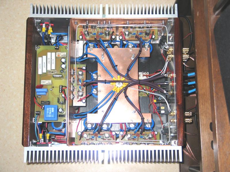
You see it was possible to make it out, at lower right corner output BJT there's still reserve to widen collector track for the final PCB layout.
PCB now looks very "professional" DIY if that is the right expression, it is so complex that topology schematic is not obvious at the first sight. Very impressive I love it, and logical question would be, when are you gonna make it working? 😀
Hi Marc 😉
You see it was possible to make it out, at lower right corner output BJT there's still reserve to widen collector track for the final PCB layout.
PCB now looks very "professional" DIY if that is the right expression, it is so complex that topology schematic is not obvious at the first sight. Very impressive I love it, and logical question would be, when are you gonna make it working? 😀
Yes it was possible, your experience hat the final word... I know there still little space at this BJT but for keeping symetrie as i can't more at upper i let so the lower.
To answer at you question "when" : i begin a bom on mouser so the major parts. nd i need to more order to complet the whole BOM. The point i must clarify before order to mouser, is the IRF640/9640 selection process. I have on hand between 10 and 15 unit of each beut need to choose the good or purchase new if there is no good.
For instance i have trafo, 4 inline 25A rectifier bridge, 4x22.000uF 63V smoothing cap (wanted 4 more to have rock solid PSU for min 3 ohms speakers), Heatsink ( 2u of 265x140x75mm), BIGBT match MJL3281A/1302A, 0R22 MCP71 and 2N5486/5462 are ordered. If i can fix IRF driver i can order next week mouser and in same moment the orther 2 order for Epoxy plate, TLP621, some wima MKS...The goal is to have a pototype to hear the most rapidly, a finished amp inDIY box need much more time
EDIT : R1, C1 value need to be fixed to.
Marc
Last edited:
Yeah good plan to hear prototypes as soon as possible, in the mean time waiting for material, you can produce two PCBs.
Try to stay at parts stated in original sch, otherwise it would be fine to discuss about any improvement part. There are many in the market but practical experiences confirmed that chosen ones are very good. BIGBT driver mosfets can be replaced with Toshiba's TO-220 mosfets as improvement but are not easy to find. TLP627 cannot be replaced with TLP621, please order TLP627-4 as an apropriate optocoupler.
Input BC's matching is also very important, as much hFE as possible and the same number for NPN/PNP. VAS KSA/KSC selection is also crucial, etc.
So good fun I wish you here, regards Andrej 😉
Last edited:
Do you plan to use optional +/- 10 V rails for the front-end. It would be a significant improvement for a little cost involved, also the output's stage efficiency would go to maximum. 😉
Last edited:
Yeah good plan to hear prototypes as soon as possible, in the mean time waiting for material, you can produce two PCBs.
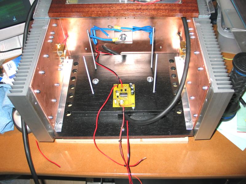
Thats what i have in idea. I have to progress on the soft start board and speaker protect board to have same aesthetiques level as TSSA
Try to stay at parts stated in original sch, otherwise it would be fine to discuss about any improvement part.
I can't go different, not aware enough with electronic conception. Do i keep SSA value for R1/C1 in TSSA?
BIGBT driver mosfets can be replaced with Toshiba's TO-220 mosfets as improvement but are not easy to find
And expenssive as we must process to matching. It would be nice if you can detail your matching process for BIGBT driver (maybe with matching circuit diagram).
TLP627 cannot be replaced with TLP621, please order TLP627-4 as apropriate optocoupler
only Typo mistake, i have TLP627 on my BOM
Input BC's matching is also very important, as much hFE as possible and the same number for NPN/PNP. VAS KSA/KSC selection is also crusial etc.
Sheet that was not in my mind, i just go to order more than the 10u of each note on my order...(on semi for input and fairchild for VAS), add 10?...20?...30?. I have in mind that it is quite difficult or need a udge batch of each to match NPN/PNP HFE
So good fun I wish you here, regards Andrej 😉
Even i most aware with pratical that theorical, i wont' ignore your advices on my futur mork as your SSA Job is so astonish.
Marc
- Home
- Amplifiers
- Solid State
- TSSA - The Simplest Symmetrical Amplifier