Thank you very much Elvee,
Out of topic : Built ESP -P3A using tip35 and tip36 (Alexmm pcb- +-28V DC, 50ma bias)
compared with Circlophone side by side . For me Circlophone wins hands down. I don't have scope test to prove my views as just learning to measure amplifier using small hand held oscilloscope .
Regards
Goutham
Yes, I was refereeing to Zobel in series with output, I have not shunted it by coil.Which resistor are you talking about? There is normally only the zobel in series with the output, and it is shunted by a coil
Will do this and let you know the results.This looks like a violent load-dumping event. It could happen in case of severe clipping and highly reactive speakers.
A fix would be the addition of anti-kick-back diodes across the C & E of each output transistor; 1N4004 are sufficient, but you can also opt for larger (3A) diodes and fast types. Connect them with the cathode to the collector obviously
Out of topic : Built ESP -P3A using tip35 and tip36 (Alexmm pcb- +-28V DC, 50ma bias)
compared with Circlophone side by side . For me Circlophone wins hands down. I don't have scope test to prove my views as just learning to measure amplifier using small hand held oscilloscope .
Regards
Goutham
If it suits your sonic tastes, why not, it will result in an intermediate type of drive, between voltage and current, but then at the very least, you should use a resistor of sufficient power, ~1/4 of the theoretical output power.Yes, I was refereeing to Zobel in series with output, I have not shunted it by coil.
This makes the failure more bizarre, because any kick-back should have been seriously attenuated
What is influence of actual voltage drop across D4, D5? A typical Schottky contact has forward voltage around 0.7 Volts to this adds the voltage drop of contact resistance. I think at 3 amps U forward cannot be lower than 0.5 volts. But why should u forward be lower? Why not - easy to get - 0.7 volts?
Beyond approx. 400mA in R8, R24, the numerical value of the current does not need to be known, it is thus necessary to clamp the voltage to avoid excessive I²R losses.
Schottky's are ideal for that, because they limit the power dissipated in the resistors, they are extremely fast, and they allow 0.5V more swing at the output.
Schottky's are not required, they are just more advantageous. Circlophones have been built with ordinary Si diodes (fast), Terranigma did, IIRC
EDIT
One might argue that by using lower resistors value, one could dispense with the diodes completely, but handling mV voltages requires careful matching, and it also reduces the gain of the circlo bias engine.
As I wanted to keep the C easy and cheerful, I used diodes
Last edited:
ok. but using standard Schottky rectifier diodes it is beyond 700 mA and that - besides output swing - matters not?Beyond approx. 400mA in R8, R24, the numerical value of the current does not need to be known, it is thus necessary to clamp the voltage to avoid excessive I²R losses.
Schottky's are ideal for that, because they limit the power dissipated in the resistors, they are extremely fast, and they allow 0.5V more swing at the output.
Btw i need to modify the standard Circlophone such that the output impedance is adjustable between "zero" Ohms and some hundred Ohms. I found that particular broadband speakers appear to "like" some current drive. How to do that in a simple fashion? So far no pcb just breadboard wiring
Better to have some improvement than none at all...ok. but using standard Schottky rectifier diodes it is beyond 700 mA and that - besides output swing - matters not?
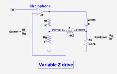
Here is an example: it is not specific to the Circlophone, and can be used with most "regular" amps having inverting and non-inverting inputs.Btw i need to modify the standard Circlophone such that the output impedance is adjustable between "zero" Ohms and some hundred Ohms. I found that particular broadband speakers appear to "like" some current drive. How to do that in a simple fashion? So far no pcb just breadboard wiring
The potentiometer allows for an impedance variation comprised between Znom/(Gain-1), in this example 0.376Ω, and near ∞.
There is thus a floor to the output resistance, but I don't think it matters much: it is equivalent to a few °C variation of the voice-coil.
Achieving zero or even negative resistances would be possible, but would involve the NI input (tricky...) or an external opamp.
The concept of Znom is required, even if the speaker has a wildly different value at some frequencies, because a comparison base for equal power levels between voltage and current modes is needed.
Note that with this simple scheme, the DC offset voltage of the Circlophone will be amplified by the gain, meaning you should preferably match the input transistors.
DC elimination would of course be possible, but would require another layer of complication
Attachments
[QUOTE
Here is an example: it is not specific to the Circlophone, and can be used with most "regular" amps having inverting and non-inverting inputs.[/QUOTE]
yes that i standard for testing but if employed in a driver amp in active speaker two feedback loops are mandatory a dc feedback and an ac feedback loop.
At Post#1, I have removed all of the offsite links (because links to other sites degrade over time).Will somebody (chiefly @ Daniel!) please point me to the Gerbers of Alex and Abetir versions of the PCB -- I assume they had been posted earlier.
Unfortunately the links on Page-1 are not working
After that I checked all of the on-site links that point to pages at diyaudio.com. I opened every one of them, and they all work, if you're logged in.
Even so, previously, the forum has gone through phases of rendering internal links correctly or not. The usual error is that it will "near miss" and you'd have a bit of scrolling to do; however, it can sometimes miss by far. In that case, there is a http://www.diyaudio.com/forums/forum-problems/ place to report forum software errors.
Links to particular posts are often useless on this forum because they relate to page number and every user can set different number of posts to show per page (10, 20, 50...) so the links will correlate precisely only when link-poster and link-clicker have the same posts per page setting.
Quoting a post number (for example #370, shown in upper right corner of the post field) is much better pointer to particular post.
Quoting a post number (for example #370, shown in upper right corner of the post field) is much better pointer to particular post.
Ouput device data from Elvee:
Higher quality score = more suitable
2SD1047_____Quality Score:__1.76
MJ(L)21194__Quality_Score:__1.60
MJ(W)21196__Quality_Score:__1.45
MJ15022,4___Quality_Score:__1.20
BD249C______Quality_Score:__1.04
MJ15003_____Quality_Score:__0.94
MJ802_______Quality_Score:__0.71
MJ15015_____Quality_Score:__0.55
MJE3055_____Quality_Score:__0.46
TIP41_______Quality_Score:__0.43
2N3055______Quality_Score:__0.35
TIP33_______Quality_Score:__0.34
BD911_______Quality_Score:__0.29
TIP3055_____Quality_Score:__0.16
Lower quality score = less suitable
So, good devices from this table include: 2SD1047, MJ21194, MJL21194, MJW21194, NJ21194, NJL21194, NJW21194, MJ21196, MJL21196, MJW21196, NJ21196, NJL21196, NJW21196, MJ15022, NJ15022, MJ15024, NJ15024, BD249C, MJ15003, NJ15003, MJ802, NJ802. Can you find any of these?
I am little puzzled here. 2SD1047 is ranked on top which has ft of 20Mhz, but overall circlophone design principle suggests to use slower devices (<4Mhz).
 .
. Yup.. Building circlophone again with only the best components suggested by Elvee.
Regards ll
To be honest, I do not exactly remember the precise details of the equation leading to these scores, but I certainly didn't work it out lightly, and I don't disavow it in anyway.
There might be some misunderstanding here: the Circlophone was designed with slow devices in mind, typically the 2N3055, scoring ~0.35.
This means that it won't oscillate or misbehave with these devices, and it will even tolerate slower devices, but of course, in our real material world you cannot change lead into gold (well, in fact you can, but it is impossibly costly), and whilst using slower devices is possible, they will reduce the amount of GNFB available at higher frequencies, meaning a higher 20k THD figure.
Is it problematic? That's for you to judge: how well can you hear the 20k harmonics? How important for you is the HF performance?
I take no sides, but I attributed a better score to better devices in this respect, as I did for SOA for example.
In summary, the score takes into account a number of factors, including today's builders preferences, but it is certainly not an index of the final audible qualities of the amp: robustness and other factors are also included.
What I certainly never meant is that slower devices will lead to better performances: slower devices will work, and the difference with faster ones will not be extreme, except perhaps for extremely slow devices (Ft<100kHz), but even then, the difference doesn't seem to be overwhelming, since a member (terranigma) built a C based on these devices and liked it.
If you use faster devices, the C's topology will accept them, but the amplifier will become more sensitive to local problems: long, loose wires to the OP devices may lead to local instabilities, but that's certainly not something unusual or unexpected.
Transistors like BD249 or MJ15003 have a score of ~1, meaning perfectly OK, but they are slow enough to be almost instability-proof: they look like an ideal compromise.
I built C's with those 2SD1047's because they were cheap and have good specs. They were just fine, at least I couldn't observe something catastrophic. The only problematic ones that I remember was 2SC5200's. You probably know that what "C" means in Japanese transistors.
I didn't hesitate to build with 200khz devices and also with HEXFETS. They were just fine too, differences were subtle if used same small transistors on remaning sections. According to my experience, Circlophone builders should have concentrate on small signal transistors, especially those ones at bias servo. These are the ones defining sound character in my opinion.
I didn't hesitate to build with 200khz devices and also with HEXFETS. They were just fine too, differences were subtle if used same small transistors on remaning sections. According to my experience, Circlophone builders should have concentrate on small signal transistors, especially those ones at bias servo. These are the ones defining sound character in my opinion.
Thank you very much for the detailed explanation Elvee.
Thanks for your inputs Terranigma.
Since I will be using circlophone for high frequency also (in a biamped set up with linkwitz active crossover) decided to go with Njw21194. And Bc556b for inputs and ksa1845 for sensors . This time I will be supplying with 35V rails. All the active devices will be procured from RS component so that authenticity is guaranteed. My last setup which had tip35c(st) was procured locally and failed authenticity test suggested by Eva. Which may be the reason for failure of my earlier circlophone set up(extreme load dumping event explained by Elvee few pages back).
But even with the fake devices circlophone performed exceptionally well. As per my friends who had listened to circlophone set up (one of them is a Indian classical musician who performs in small concerts) had told me music reproduction is very close to live performances without a hint of listening fatigue.
and ksa1845 for sensors
Sensor transistors are running in Class-A, thus power and heat dissipation requirements probably will be higher than what ksa1845 can provide.
Sensor transistors are running in Class-A, thus power and heat dissipation requirements probably will be higher than what ksa1845 can provide.
Thanks Terranigma, then what is your recommendation for Q12, Q13 on 35v rail. I modified Alexmm pcb to take ksa1845
and my pcb are shipped. Please note that mine is original circlophone as Elvee published. Only difference is rail voltage.
Last edited:
Sensor transistors are running in Class-A, thus power and heat dissipation requirements probably will be higher than what ksa1845 can provide.
Thanks Terranigma, then what is your recommendation for Q12, Q13 on 35v rail. I modified Alexmm pcb to take ksa1845
and my pcb are shipped. Please note that mine is original circlophone as Elvee published. Only difference is rail voltage.Mr Gouthama,
From where you got the pcb fabricated in India and at what price?.
I etched it myself, you can try jlpcb.
- Home
- Amplifiers
- Solid State
- Building Elvee's Circlophone: Documentation, Parts, Accessories, & beginner friendly