


With extraneously fast output devices, Click Here and install C11I'm using 2SC5200/A1943 for the output
I will edit post 1 and add this to the notes section. Thank you for the helpful questions that have been nice for improving the documentation.
It is not because of the power amp. It is to reduce turn on and off thump from single rail sources. A normal Circlophone doesn't power thump, but a normal computer does. My computer is set for standby power saver and the computer outputs big thumps when it wakes up.You have mentioned "thump stopper accesory", do you also mean at turn on & off?
Okay. Here is a piece of the proposed new input system. The added BAT86 are for reducing offset bounce (without needing the trimmer accessory). The added 3.3v zener and 39R are the thump stopper (for thumping sources). Zener are capacitive, about 0.8n when in series like that, and it also blocks RF as well as blocking HF noise from the source. The added parts are accessories that you may (or may not) like. The following attachment has experimental status.Can you please show it to me in the schematic..
Attachments
Last edited:
I and several others need a briefing (directions) on how to make a PCB. Help?
You can find information on the subject on this site:
DIY Printed circuit board
There are many different ways of doing it, just chose your preferred one. Have fun.
You can find information on the subject on this site:
DIY Printed circuit board
There are many different ways of doing it, just chose your preferred one. Have fun.
My apologies. Could you double-check the replacements (attached)?Daniel, in your schematics Q5 and Q6 are reversed. It may not mean much, but it might create some confusion.
Attachments
Last edited:
RF immune had to do with layout on the Wakabi board.
http://www.diyaudio.com/forums/solid-state/189599-my-little-cheap-circlophone-2.html#post2590488
Building on a PCB would be a lot easier than a perfboard build.
My perfboard layout was not RF immune until I changed the input just like post 102 above. The capacitance at the input load resistor is increased by the added overload blocker zener arrangement that averages 0.78n of diode capacitance for series pair of most glass bodied zeners. Bit of low parts count goodness there. Best to check with capacitance port of digital multimeter, but I checked quite a few zeners and they were all close. Technically, the trick is to use quiet signal zeners; however, I've almost 50x gain and ordinary zeners didn't make noise (tis damped by the 10k and caught in the 330p anyway). If you just need to remove RF, an ordinary capacitor there could do it more simply.
Last edited:
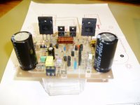
NOS 2N3772's and BD183's located
It will be an "old school" build, sine the donor chassis is a 60W professional amp with TO3's at the outputs. PSU will be reused, possibly with a recap.
That's the same spirit of mine regarding to the Circlophone. The unique topology makes it is feasible to use what you have until respecting the specs. It is very interesting approach of that possibility of using old fashion TO-3 devices, quality transistors from golden era in a new design. I think that each build is coming to having its own characteristics somehow.
I struggled with some scholarship for a duration. I plan alternate the PCB if I could find an opportunity. CFP pcb is a product of a reputable process and cooperation in my opinion.
The 2N3772 are really too slow, they will work but HF performance will be abysmal.PCB's in progress. I don't think I ll need the R-L at the output, since I ll be using such slow power transistors. And yes. I actually fond them in the local shops.

The BD183 are not exactly fast, but they are 4 times faster, that is an improvement.
Also, I don't recommend using the CFP version, it is less clean than the official version.
You can wire your CFP PCB as a normal one (or you can try both and compare).
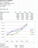
Measurement results CFP Circlophone
Last week i have done some real life measurements on the CFP Cirlophone.
Attached files show the specs.
have fun building.
regards,
Piersma
Last week i have done some real life measurements on the CFP Cirlophone.
Attached files show the specs.
have fun building.
regards,
Piersma
Attachments
- Home
- Amplifiers
- Solid State
- Building Elvee's Circlophone: Documentation, Parts, Accessories, & beginner friendly