Hi Elvee/Daniel,
I would like to build a circlophone with Sanken 2SC2922s. Elvee says here that they are very good choices provided the layout is good and the compensations are in place. Can you tell me which of the available board designs are the best for using these devices? If none are suitable, can you tell me what modifications I need to make to make them work? Would I need to use a specific driver?
The On Semi devices would be cheaper, but I am fascinated by these devices and they are easily available here through element14.
Powerflux's version looks like a good candidate for fast devices:Can you tell me which of the available board designs are the best for using these devices? If none are suitable, can you tell me what modifications I need to make to make them work? Would I need to use a specific driver?.
http://www.diyaudio.com/forums/solid-state/189599-my-little-cheap-circlophone-38.html#post2839948
Good drivers among those listed are suitable. Be careful not to use fakes, there are so many around....
I guess this is the correct thread for posting messages with regards to build in progress...")
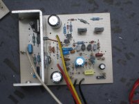
After replacing parts and following terranigmas correction (terranigma has a keen eye on spotting details (eagle eyes!..) Here's my build so far, DC-offset measured at 01.8mv but the lowest was 00.6mv... but at times changing and the highest was about 02.00mv. At + rail collector voltage was at 21vdc and at - rail base & emitter voltage was at 21vdc. At phase-splitter I replaced the 2N5551 with BC547 but they seem to be fine none got shorted...hmm..strange though
  I decided to replace the 12v zeners for 0.5watts just to confirm if the 1 watter zeners was also creating problems. VAS trannie warms a bit after about 20mins but BD drivers are getting hot even with the heatsink around I think they won't survive. I used 2SC5200 for the output (they remain cold to touch) I think I'm sensing bias problems, can the 10k offset be increased? Could the 2SC5200 creates the problem?
Now I may have to ask a noob question did I measure the output voltages right? and how do I properly measure the idle current, sorry I am not so familiar with quasi's. Was it across R10 & R56?
After replacing parts and following terranigmas correction (terranigma has a keen eye on spotting details (eagle eyes!..
) Here's my build so far, DC-offset measured at 01.8mv but the lowest was 00.6mv... but at times changing and the highest was about 02.00mv. At + rail collector voltage was at 21vdc and at - rail base & emitter voltage was at 21vdc. At phase-splitter I replaced the 2N5551 with BC547 but they seem to be fine none got shorted...hmm..strange though I decided to replace the 12v zeners for 0.5watts just to confirm if the 1 watter zeners was also creating problems. VAS trannie warms a bit after about 20mins but BD drivers are getting hot even with the heatsink around I think they won't survive. I used 2SC5200 for the output (they remain cold to touch) I think I'm sensing bias problems, can the 10k offset be increased? Could the 2SC5200 creates the problem?Now I may have to ask a noob question did I measure the output voltages right? and how do I properly measure the idle current, sorry I am not so familiar with quasi's. Was it across R10 & R56?
Attachments
Last edited:
I've updated post #1 with the means to check the idle current (it is located in with the resistors).
Did you use a gray Philips BD139 (COB=6pF) for Q5 Q6? Surely those will work better than fake Hitachi devices and don't expect any sort of reasonable results or temperatures until you remove the fake devices. Why not start out with 2N3019's or 2N1893's for Q5, Q6 to absolutely assure that this section is working as expected?
Are you testing with output devices connected? I ask because you will need some outputs prior to power up, else the amp will overheat quickly. I got some BD911 and some MJE3055 for smoke tests. If no smoke then I can put on the MJL21194's later.
The MBR735's need shoulder washers and thermal pads if you want to mount them onto the heatsink--the PCB is arranged that way to help hold the heatsink stable. The authentic Philips BD140's have those soft copper leads and those need the added help to hold up the driver heatsink.
Well, I hope this helps.
When the capacitor reads 821 it is 820pF, but if it reads 822 it is 8200pF.. . . 821pf.
Ah, well, like this chart that was hung on the wall near the desk:
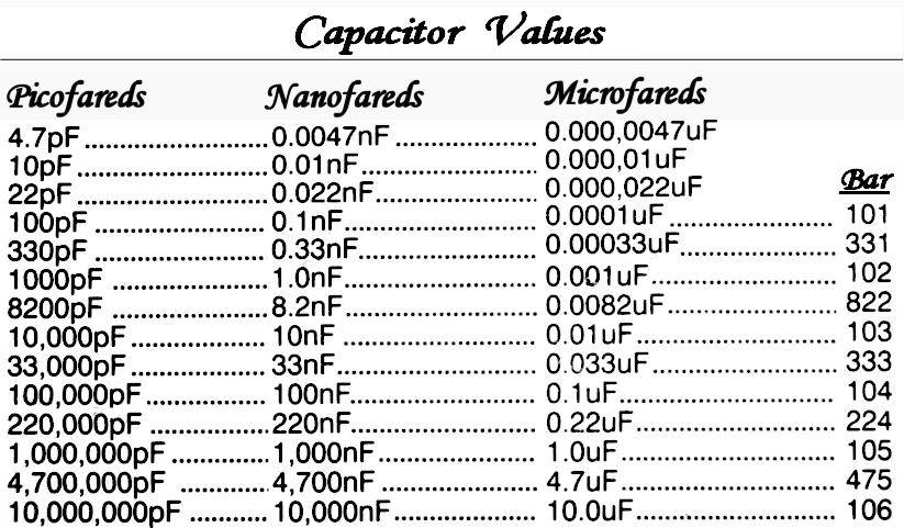
(click image to enlarge)
I guess this is the correct thread for posting messages with regards to build in progress...
After replacing parts and following terranigmas correction (terranigma has a keen eye on spotting details (eagle eyes!..
Now I may have to ask a noob question did I measure the output voltages right? and how do I properly measure the idle current, sorry I am not so familiar with quasi's. Was it across R10 & R56?
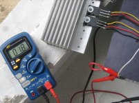
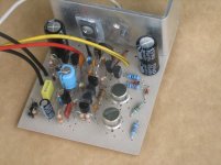
Good to see measure healthy offset values. That heatsink looks very fit and nice! It means that you can connect a test speaker and begin to play some music. I see you are using wires for easy testing power transistors. I suggest you to keep those wires short as much as possible.
Are you sure that BD140's won't survive? That's right, they are getting hot but it wouldn't be a problem if temperature stood still for enough amount of running time. Those stain on metal plates at BD140's should be removed due to sufficient heat transfer.
As I mentioned earlier, I suggest you to use slower device for output. You can't be sure that 2sc5200 is causing a problem or not if you don't observe output with oscilloscope. For example, 3mhz BD249C's are very suitable transistors for circlophone. I tested Bourns brand of BD249C (they were made in Philippines) and their sonic behaviour was outstanding.
According to Elvee's latest experiments, low pass filter capacitor's value is 8.2 nF. See the C4's value of 3rd picture at related post.
Last edited:
Thanks!Those stain on metal plates at BD140's should be removed due to [in]sufficient heat transfer.
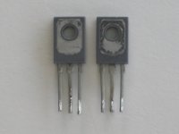
Q9, Q11: Yes, Philips BD140's that have been corroding since 1987 need some black sandpaper (like 600 grit, very fine grain) to "lap" the thermal interface surface and shine it up, thus removing most of the corrosion. Then they do need some thermal paste (and pads). Thermal paste, such as Arctic, will prevent future corrosion.
Q5, Q6: If TO126 size (Philips BD139, Toshiba 2SC3421) are used at Q5, Q6, they might be more comfortable with some little heatsinks, such that free aluminum circle from the bottom of the beer can or some TO126/TO220 economy size little heatsinks, or even some recycled metal will do. Huge heatsinks aren't required at Q5, Q6, but plastic devices need some means to get the heat out of them. The exception is 2SC5171 since it is a physically large TO220, doesn't need a heatsink at Q5, Q6.
Concur. I believe that Elvee also ran some of the BD249C's on his own amplifier. These outputs are also suitable: 2N3055, MJ15015, MJ802, MJL21194, MJW21196, MJ21194, MJ21196, MJ15022, MJ15024, MJ15003. Surely you can find some?As I mentioned earlier, I suggest you to use slower device for output. You can't be sure that 2sc5200 is causing a problem or not if you don't observe output with oscilloscope. For example, 3mhz BD249's are very suitable transistors for circlophone. I tested Bourns brand of BD249C (they were made in Philippines) and their sonic behavior was outstanding.
Edit:
I'm trying to say: "Stable first, postpone trying unusual parts until later."
Last edited:
That is perfectly normal for discrete devices: it is equivalent to less than 1°C difference between transistors, and random variations caused by draughts for example reach easily that level.DC-offset measured at 01.8mv but the lowest was 00.6mv...
The quiescent dissipation in the drivers is ~1W, and increase with signal, so nothing abnormal.but BD drivers are getting hot even with the heatsink around I think they won't survive. I used 2SC5200 for the output (they remain cold to touch) I think I'm sensing bias problems, can the 10k offset be increased? Could the 2SC5200 creates the problem?
If you have doubts about the 2SC5200, try a slower device, TIP3055 or BD249.
About the low pass capacitor, I advise against actually using 8.2nF: it was meant as an illustration with a test signal, but for actual use, such a high value could cause excessive roll-off if the source impedance is much larger than 470 ohm.
Anyway, normal audio signals do not contain 10ns maximum amplitude edges.
It is good to you point out this issue Elvee. I was a bit curious about that high filter capacitor value. You mean we can stick with 330pF until an official version provided by yourself? I think that CFP edition rises attention due to its unique features.
Also, you didn't mention about stability margin variance after latest compensation value changes. I hope that any counter productive effects didn't occur.
Did you use a gray Philips BD139 (COB=6pF) for Q5 Q6?
Nope, I don't have it at hand, 2N3019 is currently out of stock, I might as well check on the BD139 they are complement to BD140.
Are you testing with output devices connected?
Yes, I actually did a quick test without the outputs, BD140 gets hot real fast.
Good to see measure healthy offset values. That heatsink looks very fit and nice!
Thanks, I got them from a discarded PC PSU I was surprised to see that it was exactly the same width with the board.
I see you are using wires for easy testing power transistors.
I always do this when testing my build, for convenience saves time and when something when wrong with the output it won't damage other parts and the PCB as well..
Are you sure that BD140's won't survive
Well, I am not exactly so sure about the maximum heat dissipation of the device but I think but for longer hours of use, they cannot hold on.
As I mentioned earlier, I suggest you to use slower device for output. I tested Bourns brand of BD249C (they were made in Philippines) and their sonic behaviour was outstanding.
I will see if I can find those BD249C here, I do know however that semiconductors manufactured here is hard to obtain. They are being exported to other countries
.
Originally my plan was to use TO-220 devices for Q9, Q11 but the CFP board cannot accomodate it, the footprints were rather small for TO-220 (I hope piersma is working on his design...
)That is perfectly normal for discrete devices: it is equivalent to less than 1°C difference between transistors, and random variations caused by draughts for example reach easily that level.
The quiescent dissipation in the drivers is ~1W, and increase with signal, so nothing abnormal.
If you have doubts about the 2SC5200, try a slower device, TIP3055 or BD249.
About the low pass capacitor, I advise against actually using 8.2nF: it was meant as an illustration with a test signal, but for actual use, such a high value could cause excessive roll-off if the source impedance is much larger than 470 ohm.
Anyway, normal audio signals do not contain 10ns maximum amplitude edges.
Thanks for the feedback Sir Elvee.
See also post #7 for a larger listing. Oh yes, it would be good to put some useful devices at Q5, Q6 before proceeding further.Nope, I don't have it at hand, 2N3019 is currently out of stock, I might as well check on the [Philips] BD139. . .
P.S.
I'm working on a clear CFP Circlophone schematic.
Last edited:
P.S.
I'm working on a clear CFP Circlophone schematic.
Good to hear that, this is going to be a lot of help!
While at work I've been contemplating
on my build, figuring what could be the error..If my hint was correct, it is probable that VAS D669 is pushing the BD140 drivers hard. I think It should work the other way, where drivers should be the stronger ones than the VAS. Probable solution is to either replace VAS D669 with (say) BD139 or replace drivers BD140 with the stronger B649. Using fakes is a possibility too for they could be insufficient to handle the job.Anyway I may have to confirm this, in the coming weekend (DIY time!
) just a thought though....It looks like I'm in big trouble right now, I just worked on my amp again and following the latest mod according with Daniels CFP Schematic here's what the amp say's..
Idle current, measured across R8/R11= 0.12ma
DC offset = 30.0mv when measured at AC = 15.0v
I've lost two 5.6 ohms resistor at Zobel network, they instantly went up in smoke right at power on. I am now using D1047C for the output and they heat-up fast.
I used 2N5053 for VAS 'found them at one local supplier and the specs was very close to 2N2219 but I don't think the amps having problems at VAS. Drivers and VAS are less warmer, better than my previous set-up using D669A. I have tried to dissect the whole thing but after finding a few parts with no signs of fault I gave up.
All help will be appreciated!
That amp is oscillating with that 15v of noise. Question: Was it THIS schematic: CFP Circlophone I really need to know.
If so, then may I suggest using a Standard Circlophone schematic yet also getting almost all of the advantages of the CFP by simply using BC560C input pair at Q3, Q4 instead of all that hullabaloo?
If so, then may I suggest using a Standard Circlophone schematic yet also getting almost all of the advantages of the CFP by simply using BC560C input pair at Q3, Q4 instead of all that hullabaloo?
The link yes, I double-check that with Sir Elvees' correction,.. looks OK to me.
Actually I'm saving my spare parts for the official circlophone (to date, according to Elvee) I plan to use AlexMMs lay-out. I just can't give-up on the CFP....anyway..
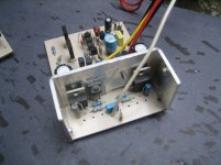
Here's the revised amp..
Actually I'm saving my spare parts for the official circlophone (to date, according to Elvee) I plan to use AlexMMs lay-out. I just can't give-up on the CFP....anyway..
Here's the revised amp..
Attachments
- Home
- Amplifiers
- Solid State
- Building Elvee's Circlophone: Documentation, Parts, Accessories, & beginner friendly