Have you thought about putting some hysteresis around your comparators to help it to make up its mind and switch cleanly?
jan
Ooeps
 now I see
  you are thinking about the relay driver. O.k. I will fix that (it still has some other problems, like asymmetric discharge of the timing capacitor, and it needs to use an normaly open relay).
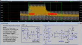
This may be the truly final one, the response times are very near the theoretical limits, for the 10 Hrz max output signal it is now down to 58 mS (where 50 mS is the lowest possible). Anyway, as before, I would appreciate comments.
The one thing that I still have to do is select an relay. So if you have an idea witch one to use, then let me know. It may be a bit expensive (let’s say up to 40 Euro (50 $ US)) but I would like an contact resistance below 50 mOhm (near 10 mOhm if possible).
.param Rref 75
.param Fv4 5Hrz; Amplifier opperating frequency
.step param Vv7 list 8m 25m 50m 100m 250m 500m 1 2
;.param Vv7 8mV; Reaction time 19 S @ offset 80mV; Min detect
;.param Vv7 25mV; Reaction time 2.7 S @ offset 250mV
;.param Vv7 50mV; Reaction time 1.3 mS @ offset 500mV
;.param Vv7 100mV; Reaction time 692 mS @ offset 1V
;.param Vv7 250mV; Reaction time 294 mS @ offset 2.5V
;.param Vv7 500mV; Reaction time 267 mS @ offset 5V
;.param Vv7 1V; Reaction time 116 mS @ offset 10V
;.param Vv7 2V; Reaction time 114 mS @ offset Vrail; Total failure
;.param Rref 38
;.param Fv4 10Hrz; Amplifier opperating frequency
;.step param Vv7 list 4m 25m 50m 100m 250m 500m 1 2
;.param Vv7 4mV; Reaction time 18 S @ offset 40mV; Min detect
;.param Vv7 25mV; Reaction time 1.2 S @ offset 250mV
;.param Vv7 50mV; Reaction time 648 mS @ offset 500mV
;.param Vv7 100mV; Reaction time 347 mS @ offset 1V
;.param Vv7 250mV; Reaction time 148 mS @ offset 2.5V
;.param Vv7 500mV; Reaction time 135 mS @ offset 5V
;.param Vv7 1V; Reaction time 60 mS @ offset 10V
;.param Vv7 2V; Reaction time 58 mS @ offset Vrail; Total failure
Attachments
a new strtegy to compare to your existing.
The DC servo when fed from +-15Vdc will have a maximum range of output (correction) voltage of about +-13Vdc.
When the amplifier is working properly and there is no external DC voltage leaking in I would expect the DC servo's output correction to be <=+-100mVdc.
If the correction becomes larger then something is going on that should not be happening.
If the correction reaches either of the +-13Vdc limits the Servo can no longer correct the error and the output offset goes off scale.
apply your window comparator without any filtering to monitor the servo correction voltage. If the window comparator is set to +-12Vdc then the servo is still controlling but there is a serious fault. The comparator shuts down the output, BEFORE the damage is done.
Except when it is a fast failure when the servo's own filter will delay the detection of the excessive correction voltage.
This strategy has only one filter in the system. It should react as quickly as any other, and maybe faster.
You can add on bells and whistles. eg input mute, rail shutdown, output relay isolation, locking relays etc. Each can be triggered by either input offset, or output offset.
Last edited:
a new strtegy to compare to your existing.
The DC servo when fed from +-15Vdc will have a maximum range of output (correction) voltage of about +-13Vdc.
When the amplifier is working properly and there is no external DC voltage leaking in I would expect the DC servo's output correction to be <=+-100mVdc.
If the correction becomes larger then something is going on that should not be happening.
If the correction reaches either of the +-13Vdc limits the Servo can no longer correct the error and the output offset goes off scale.
apply your window comparator without any filtering to monitor the servo correction voltage. If the window comparator is set to +-12Vdc then the servo is still controlling but there is a serious fault. The comparator shuts down the output, BEFORE the damage is done.
Except when it is a fast failure when the servo's own filter will delay the detection of the excessive correction voltage.
This strategy has only one filter in the system. It should react as quickly as any other, and maybe faster.
You can add on bells and whistles. eg input mute, rail shutdown, output relay isolation, locking relays etc. Each can be triggered by either input offset, or output offset.
There is no way in the world that you can react in less than '1/2 * 1/Hrz' seconds (that is 50 mS for 10 Hrz (actualy 58 mS)) this exactly what my circuit does. If you are going to allow 5Hrz then the reaction limit will be 100 mS.
If you have a look at the diagrams (servo output) then you will see that you need to add some hysteresis to the window comparator and the output buffer (to filter ‘fast re-triggering’).
If you allow the DC-servo to go to full swing, e.g. 13V +/-, then it will take up to a few minutes to recover/return to below the detection limits. That is what is prevented by D6 and D7.
If you remove D2 and D5 the your detection limit will be lower, due to the fact that AC then is an even larger portion of the input signal (to the integrator).
Last edited:
read again.
I do not 'get' what you are trying to tell here, are you talking about making it respond faster ... or a simpler circuit ... then show it.
I am interested, and eager to know.
I am not talking about changing, nor modifying your existing design.
I am suggesting an alternative strategy (sorry for the typo).
Then show me something
Attachments
Last post 2012 ...
Any news on fast DC protection ?
Not many (if any) HP amps come with DC protection , meaning not the DC servo that corrects small offsets , but real fast protection for when the ouput of the opamps breaks down or somewhere else goes wrong and forces the output to produce several volts to even the supply rails (-/+ 15 V) . HP's will not survive big currents from the outputs or shorts from the supply rails to the HP's for long.
The window comparator behind an RC of about 0,5 to 1 second for around -/+ 300 mV admissible DC , is pretty easy , but how to get real fast responce time for DC voltages of more than maybe 3 V or currents larger than ~ 50 mA DC ? ( 3V 300 ohm HP = 30 mW , 30 ohm HP = 300 mW which for the 24 to 32 ohm HP will be their end) .
Painful to see HP's costing several 100's $/euro's die .
You never know how components are getting handled (ESD) and soldered for too long , which may get them to break down eventually.
Is current limiting the way to go here ?
So long as the protection is somewhat less sensitive than would detcct the 'phones maximum bass signal, it will protect fine. Any more sensitive the protection will trigger on valid signal, any less sensitive is increasing risk of damage. If the amp is way overpowered that's another issue, and the answer is use an amp better suited to the task. An overpowered amp going into oscillation could destroy someone's hearing, not just damage the voice coil, and DC protect wouldn't necessarily help.
You can also trigger protect mode on a feedback loop losing lock, not just on output voltage, although that really doesn't buy anything if you have DC protection AFAICT.
You can also trigger protect mode on a feedback loop losing lock, not just on output voltage, although that really doesn't buy anything if you have DC protection AFAICT.
Oscillation in a HP amp will be high frequency , so not much risk for ears or voice coil . The usual parallelled opamps or output buffers like BUF634 & LME49600 , are not really overpowered amps.
The feedback loop could be a good idea . Comparing the amp's input with the output , triggering a very quick responce when the difference gets too big because of a voltage offset or even oscillation.
The feedback loop could be a good idea . Comparing the amp's input with the output , triggering a very quick responce when the difference gets too big because of a voltage offset or even oscillation.
Reed relays are not intended for speaker current levels, especially NC contacts. A speaker relay should be rated for at least 10 Amps better 25 or 40 Amps. Running a 100 Watt amp through a reed relay will fuse the contacts together. If the amp already has a servo, it's possible to use the servo output, but you still have to rectify it and an op-amp is not enough current to drive a reasonable size relay. A real speaker protection circuit can be 3 or 4 transistors, actually simpler than the circuits suggested here.
An externally hosted image should be here but it was not working when we last tested it.
- Status
- This old topic is closed. If you want to reopen this topic, contact a moderator using the "Report Post" button.
- Home
- Amplifiers
- Solid State
- Amplifier DC protection