All,
This is a very simple thing that I am proposing.
For DC protection in an amplifier, that has an DC-servo circuit using an OpAmp, it would be possible to connect an reed relay (like the one below) to the output of the OpAmp, when DC is detected in large quantities the reed-relay will be activated and with the output of the relay you can deactivate the amplifier.
http://www.cotorelay.com/images/stories/2900/2900.pdf
The questions are:
Has anyone tried this before?
Did it work?
And if not, why not?
Regards,
Frans.
Post #22 Getting near the theoretical limit http://www.diyaudio.com/forums/solid-state/209896-amplifier-dc-protection-2.html#post2974055
Post #17 The new current design") can be found at http://www.diyaudio.com/forums/solid-state/209896-amplifier-dc-protection.html#post2973496
can be found at http://www.diyaudio.com/forums/solid-state/209896-amplifier-dc-protection.html#post2973496
Post #12 Current design can be found at http://www.diyaudio.com/forums/solid-state/209896-amplifier-dc-protection.html#post2972228
This is a very simple thing that I am proposing.
For DC protection in an amplifier, that has an DC-servo circuit using an OpAmp, it would be possible to connect an reed relay (like the one below) to the output of the OpAmp, when DC is detected in large quantities the reed-relay will be activated and with the output of the relay you can deactivate the amplifier.
http://www.cotorelay.com/images/stories/2900/2900.pdf
The questions are:
Has anyone tried this before?
Did it work?
And if not, why not?
Regards,
Frans.
Post #22 Getting near the theoretical limit http://www.diyaudio.com/forums/solid-state/209896-amplifier-dc-protection-2.html#post2974055
Post #17 The new current design
can be found at http://www.diyaudio.com/forums/solid-state/209896-amplifier-dc-protection.html#post2973496Post #12 Current design can be found at http://www.diyaudio.com/forums/solid-state/209896-amplifier-dc-protection.html#post2972228
Last edited:
Hi,
I am working something similar what your are suggesting. See this link to my tread and see it is the same.
http://www.diyaudio.com/forums/chip-amps/209519-protecting-speaker-output-using-microprocessor.html
I am working something similar what your are suggesting. See this link to my tread and see it is the same.
http://www.diyaudio.com/forums/chip-amps/209519-protecting-speaker-output-using-microprocessor.html
FdW,
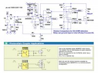
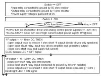
A window comparator which can detect preset lo/hi DC limits on the output is sometimes added to the DC servo circuitry. Any DC outside of the window can trigger a relay to either open(isolate speaker) or close(shunt 1 ohm in parallel to speaker), in addition to playing a role in a total power up logic.
Safe power up logic can include:
1) short input to ground until safe power-up is proven
2) allow input front-end circuits enough time to power up before the high current output power supply slow-start resistor is shorted by a relay.
3) either open up a relay in series with the speaker, or shunt a 1 ohm safety load in parallel with the speaker for protection
4) if DC is detected during operation, the output power supply relay can be opened
5) when power is turned off, shunt input to ground and shunt speaker to 1 ohm resistor to avoid "THUMP"
etc...
Attachments
Member
Joined 2009
Paid Member
some of these look pretty complicated.
You only need a few transistors.... http://www.diyaudio.com/forums/soli...imple-symmetric-amplifier-13.html#post2939602
You only need a few transistors.... http://www.diyaudio.com/forums/soli...imple-symmetric-amplifier-13.html#post2939602
FdW,
A window comparator which can detect preset lo/hi DC limits on the output is sometimes added to the DC servo circuitry. Any DC outside of the window can trigger a relay to either open(isolate speaker) or close(shunt 1 ohm in parallel to speaker), in addition to playing a role in a total power up logic.
Safe power up logic can include:
1) short input to ground until safe power-up is proven
2) allow input front-end circuits enough time to power up before the high current output power supply slow-start resistor is shorted by a relay.
3) either open up a relay in series with the speaker, or shunt a 1 ohm safety load in parallel with the speaker for protection
4) if DC is detected during operation, the output power supply relay can be opened
5) when power is turned off, shunt input to ground and shunt speaker to 1 ohm resistor to avoid "THUMP"
etc...
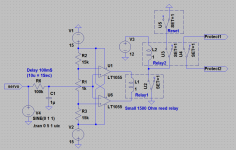
This is what I am (about) planning to do, de main differences are:
I will attach a small relay directly to the comperators output.
I did not add a second stage intergrator (only a small RC network).
For the input of the DC protect I am using the existing servo ouput.
Any comments on that?
Attachments
Can anyone tell me how fast a DC protect would need to act. Lets say the amplifier fails and produces 10 Volts DC is can not act in mSecs due to the fact that it is viable that it under normal conditions may produce 10 Hz at 10 Volts. Also when you drop the stylus on a record this produces an very low frequency 'thump' or a warped record spinning at 33 RPM will produce an .5 Hrz signal.
Also what would be the threshold for reacting, is 100 mV DC allowable, or even 500 mV. What is the lower threshold to be detected, around 200 mV (or less)?
Regards,
Frans.
Also what would be the threshold for reacting, is 100 mV DC allowable, or even 500 mV. What is the lower threshold to be detected, around 200 mV (or less)?
Regards,
Frans.
Look here, complete amp protection, a loudspeaker protection and an capacitor multiplier in one bouard: http://www.diyaudio.com/forums/solid-state/182554-thermaltrak-tmc-amp-6.html#post2910364
dado
dado
Look here, complete amp protection, a loudspeaker protection and an capacitor multiplier in one bouard: http://www.diyaudio.com/forums/solid-state/182554-thermaltrak-tmc-amp-6.html#post2910364
dado
Thanks for responding, and yes I know there are more than one ways to solve the overcurrent and DC problems. Still I would like to see answers to my questions, and also I do not want to have anything interfering with the power lines. As my amplifier is not referenced (in any way) to the power supply (is uses an separate internal shunt supply for the driving and gain stage) I opted to use the window comparator, to validate my design (on going) it would be nice to know a bit more about the timing and thresholds desirable for such a circuit.
Regards,
Frans.
Can anyone tell me how fast a DC protect would need to act. Lets say the amplifier fails and produces 10 Volts DC is can not act in mSecs due to the fact that it is viable that it under normal conditions may produce 10 Hz at 10 Volts. Also when you drop the stylus on a record this produces an very low frequency 'thump' or a warped record spinning at 33 RPM will produce an .5 Hrz signal.
Also what would be the threshold for reacting, is 100 mV DC allowable, or even 500 mV. What is the lower threshold to be detected, around 200 mV (or less)?
I set up my DC detection using a low pass filter as the input.
This filter automatically outputs a variable response depending on the amplitude and frequency of the Fault Signal.
A low frequency is necessary. It won't react to a 20Hz full amplitude signal no matter how long it is applied.
It will react to a 20Vdc signal within about 30 to 40ms.
It will react to a 3Vdc signal in about 100ms
It will react to a 5Hz signal in about 250ms for 10Vac.
Unfortunately it resets on that 5Hz signal after a second or so and then may retrigger again in 250ms. I have not yet found a way to cure this anomaly without adding components.
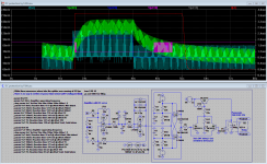
First 'final' design
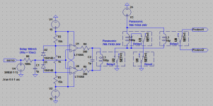
This is what I have now, it is reasonably fast it can be made to work with very specific operating parameters (see table). The first set of parameters will allow an amplifier running at 5 Hrz and full power while still detecting 190 mV output offset. The second set of measurements will allow the amplifier to run at 10 Hrz and detect (even) a 110 mV offset.
Reaction times vary, from more than 1 Sec for small offsets and down to 100 mS for large offset. Real amplifiers would switch even faster (when failing totally) due to their higher rail voltage.
The output protection relay stay's on for the duration of the DC offset event, and after that it will stay on for an extra 5 Seconds.
In the attached picture you see,
Green = Offset event
Blue = Protection relay
Gray = Servo output
I really would like to see some comments on the schema and timing results
; While these measures where take the aplifier was running at 28 Vpp
;.param Rref 76
;.param Fv4 5Hrz; Amplifier opperating frequency
;.param Vv7 19mV; Reaction time 8381 mS @ offset 190mV; Min detect
;.param Vv7 25mV; Reaction time 4771 mS @ offset 250mV
;.param Vv7 50mV; Reaction time 1962 mS @ offset 500mV
;.param Vv7 100mV; Reaction time 959 mS @ offset 1V
;.param Vv7 250mV; Reaction time 540 mS @ offset 2.5V
;.param Vv7 500mV; Reaction time 326 mS @ offset 5V
;.param Vv7 1V; Reaction time 261 mS @ offset 10V
;.param Vv7 2V; Reaction time 171 mS @ offset Vrail; Total failure
.param Rref 38
.param Fv4 10Hrz; Amplifier opperating frequency
.param Vv7 11mV; Reaction time 6685 mS @ offset 110mV; Min detect
;.param Vv7 25mV; Reaction time 2056 mS @ offset 250mV
;.param Vv7 50mV; Reaction time 990 mS @ offset 500mV
;.param Vv7 100mV; Reaction time 492 mS @ offset 1V
;.param Vv7 250mV; Reaction time 283 mS @ offset 2.5V
;.param Vv7 500mV; Reaction time 176 mS @ offset 5V
;.param Vv7 1V; Reaction time 109 mS @ offset 10V
;.param Vv7 2V; Reaction time 99 mS @ offset Vrail; Total failure
The shown solution uses a DC servo that is an existing part of the amplifier.
Attachments
Last edited:
The reaction times of 99ms and 171ms for rail voltage offset seem a bit long.
But much shorter and it would not allow the amplifier to run at 10 Hrz. You can very easily experiment with these parameters (if using a simulator program). As stated, in practical situation these values will be lower, the sample amplifier only has a rail of 15 V and the reaction time gets shorter with rail voltage (but you will need to use diodes with an higher Vak and the lower detection limit will be compromised).
Is it the 220k for R6 that gives this long time delay?
Yes, this one controls the integration time of the DC servo, it could be made a bit faster but then it starts to influence the amplifier at low frequencies. The other parameter that controls reaction time is the value of Rref.
Could you explain the operation of the network between u7 & u6?
This is an low pass filter with voltage limiter and is used to protect the DC servo from the amplifiers output voltage (normally 100 Vpp or more). The diode Vak sets the detection response, it limits the amount of AC (also DC when above 250 mV) and (at low values) it makes that the DC value is large compared to the AC value. To explain: when the amplifier runs at 100 Vpp and the offset is 100 mV the offset voltage is 0.1% of the servo input, if the signal is clipped by the diodes then the AC part will be 250 mV and the offset will be 40% of this.
P.s. U7 acts as the power amplifier and U6 is its DC servo circuit, I do not consider them part of the DC protection circuit!
Last edited:
Now I understand.
Power Amp = u7
Why inverted?
No reason, just like it happened
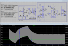
DC protection (after tuning/tweaking for speed)
First of all, I really would like to get some comments, about timing and threshold’s as in this circuit.
Attached is a measurement that shows all involved signals.
First let’s identify them all:
• Azure: Input signal 1400mV sinus (after 10 seconds) and superimposed 100mV of DC (resulting in one volt output DC) (after 20 seconds).
• Green: The resulting DC-servo output signal.
• Blue: The input DC signal (voltage source V7).
• Purple: The upper detection threshold (set by Rref).
• Gray: The lower detection threshold (set by Rref).
• Red: The protection relay (protect1/protect2).
As you can see, the minimum signal to be detected is set by the voltage that you see at 10 seconds, if the detection limit is set lower then ‘false’ detections will happen. It is possible to lower this voltage by using a larger capacitor (C4). Using a larger capacitor will lower the low frequency gain and thus the signal that is generated by the DC servo (at the time of the ‘step’-voltage, when the AC signal switches on).
Detection of DC takes place when the DC-servo output signal crosses the detection threshold (Rref). The detection threshold cannot be set lower due to the fact that then ‘false’ detects are generated. It is possible to do the detection a bit earlier by lowering the ‘step’-voltage when the AC signal is switched on (at the 10 seconds point) by selecting a larger capacitor (C4).
Whatever you do, you cannot (ever) detect any DC in a time shorter than ‘(1/2) * (1/Hrz)’, this is due to the ‘step’-response of the DC-servo (and possibly the 'Nyquist'-limit).
In addition to all this, you may think that using a sufficiently large capacitor will lower the ‘step’-response of the DC-servo (for practical frequencies) far enough to get nearer to the limit (as described above), this is not so in the sample given Vref is at 75mV and larger capacitors will force you to lower the reference voltage, at some point Vref will be lost into the circuit noise. When you get near the noise limit of the circuit, the circuit will start to trigger on spurious signals (that are always there, maybe it starts to detect alpha decay’s ).
P.s. The Azure (tst) signal looks a bit ragged-edged but that is due to the fact that I connected it to the Opamp's input instead of the 'real' input, but it still serves it's purpose
First of all, I really would like to get some comments, about timing and threshold’s as in this circuit.
Attached is a measurement that shows all involved signals.
First let’s identify them all:
• Azure: Input signal 1400mV sinus (after 10 seconds) and superimposed 100mV of DC (resulting in one volt output DC) (after 20 seconds).
• Green: The resulting DC-servo output signal.
• Blue: The input DC signal (voltage source V7).
• Purple: The upper detection threshold (set by Rref).
• Gray: The lower detection threshold (set by Rref).
• Red: The protection relay (protect1/protect2).
As you can see, the minimum signal to be detected is set by the voltage that you see at 10 seconds, if the detection limit is set lower then ‘false’ detections will happen. It is possible to lower this voltage by using a larger capacitor (C4). Using a larger capacitor will lower the low frequency gain and thus the signal that is generated by the DC servo (at the time of the ‘step’-voltage, when the AC signal switches on).
Detection of DC takes place when the DC-servo output signal crosses the detection threshold (Rref). The detection threshold cannot be set lower due to the fact that then ‘false’ detects are generated. It is possible to do the detection a bit earlier by lowering the ‘step’-voltage when the AC signal is switched on (at the 10 seconds point) by selecting a larger capacitor (C4).
Whatever you do, you cannot (ever
) detect any DC in a time shorter than ‘(1/2) * (1/Hrz)’, this is due to the ‘step’-response of the DC-servo (and possibly the 'Nyquist'-limit).In addition to all this, you may think that using a sufficiently large capacitor will lower the ‘step’-response of the DC-servo (for practical frequencies) far enough to get nearer to the limit (as described above), this is not so
in the sample given Vref is at 75mV and larger capacitors will force you to lower the reference voltage, at some point Vref will be lost into the circuit noise. When you get near the noise limit of the circuit, the circuit will start to trigger on spurious signals (that are always there, maybe it starts to detect alpha decay’s ).P.s. The Azure (tst) signal looks a bit ragged-edged but that is due to the fact that I connected it to the Opamp's input instead of the 'real' input, but it still serves it's purpose
Attachments
Last edited:
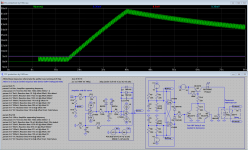
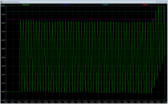
Next graph is made using an 20u integration capacitor (C4). It shows the limits of detectability. In theory, the situation shown, could detect in about ‘(1/2) * (1/Hrz)’ seconds, in this case 100mS but you need to create a low-low-low noise and ultra-clean environment to do that. The difference voltage between 'off' and 'on' is about 100uV.
It also shows that if you are not able to detect the peek at ‘(1/2) * (1/Hrz)’ seconds, then the next possible peak to detect is at ‘(1 + (1/2)) * (1/Hrz)’ seconds (it will be detectable just before it is at its peak).
The first diagram shows the DC-servo output signal.
The second diagram shows the critical parts, of the first, that determine detectability.
Attachments
Last edited:
Have you thought about putting some hysteresis around your comparators to help it to make up its mind and switch cleanly?
jan
Jan, it has R7/R8
and that works nicely (simulated).- Status
- This old topic is closed. If you want to reopen this topic, contact a moderator using the "Report Post" button.
- Home
- Amplifiers
- Solid State
- Amplifier DC protection