Which ever topology, most asume a constant current source. I have been playing with them. Two things are readilly apparent, the first is the are far more of a CCS than just a resistor. THe effectiveness of them as a ccs does vary with design quite a bit, but compared to a resistor, the worst is vastly better. THey do vary a lot by device. As I expected, you need both very fast and very high gain. No surprise.
So, here is the question: In the following plots, would you pick the design that is far stiffer, but changes radically over frequency, or the less stiff design that is very consistent? Just for reference, a standard red led is about half way between the two, a resistor is at 90dB.
So, here is the question: In the following plots, would you pick the design that is far stiffer, but changes radically over frequency, or the less stiff design that is very consistent? Just for reference, a standard red led is about half way between the two, a resistor is at 90dB.
Attachments
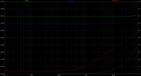
Which ever topology, most asume a constant current source. I have been playing with them. Two things are readilly apparent, the first is the are far more of a CCS than just a resistor. THe effectiveness of them as a ccs does vary with design quite a bit, but compared to a resistor, the worst is vastly better. THey do vary a lot by device. As I expected, you need both very fast and very high gain. No surprise.
So, here is the question: In the following plots, would you pick the design that is far stiffer, but changes radically over frequency, or the less stiff design that is very consistent? Just for reference, a standard red led is about half way between the two, a resistor is at 90dB.
Not an answer to your basic question, but:
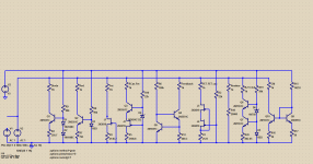
The two-FET design, to work well, needs a higher-pinchoff-voltage part for the upper device. Then your return of the upper device's gate to the lower source will work quite well indeed for much lower output capacitance at the upper drain. You may need a few more volts overall for best performance.
BTW, what is R2 doing?
Last edited:
bcarso, Good question. R2 is clearly not doing a darn thing. I think when I started, I had a resistor from gate to ground.
I am greatly hampered by the very limited models for parts. The 2N3819 is the fastest one in LTSpice. To actually use it, one needs to add a 10K resistor in the tail so it stays within it's voltage range. Small hit to performance, but better than the other models.
JCX, These were the versions I dug up. I am sure there are many more. I'll do a bit of searching on bootstrap versions. Like anything, one can keep adding parts and beat it to death. I limited it to two active devices arbitrarily. I have seen all of these in use. I'll do some searching on bootstrap versions. Extending their bandwidth would seem to be a reasonable goal.
Such a simple thing, a ccs. Humph. I just need that part that is in Spice, you know the one with two circles that works perfectly. Funny, it has no part number I guess the only way to see how transistors I might actually use work is to breadboard them. 2SC1775, 2SC2240. I really don't know about available JFETS. They seem to be very limited.
I am greatly hampered by the very limited models for parts. The 2N3819 is the fastest one in LTSpice. To actually use it, one needs to add a 10K resistor in the tail so it stays within it's voltage range. Small hit to performance, but better than the other models.
JCX, These were the versions I dug up. I am sure there are many more. I'll do a bit of searching on bootstrap versions. Like anything, one can keep adding parts and beat it to death. I limited it to two active devices arbitrarily. I have seen all of these in use. I'll do some searching on bootstrap versions. Extending their bandwidth would seem to be a reasonable goal.
Such a simple thing, a ccs. Humph. I just need that part that is in Spice, you know the one with two circles that works perfectly. Funny, it has no part number
I guess the only way to see how transistors I might actually use work is to breadboard them. 2SC1775, 2SC2240. I really don't know about available JFETS. They seem to be very limited.I am greatly hampered by the very limited models for parts. The 2N3819 is the fastest one in LTSpice. To actually use it, one needs to add a 10K resistor in the tail so it stays within it's voltage range. Small hit to performance, but better than the other models.
For the moment just put a voltage source in series with the upper FET gate, to bias that part up a few volts. It will then resemble a higher-pinchoff part.
I had made an idle promise to post some current source results a while back, but it's so buried now it doesn't make a lot of sense. Probably better to start yet another CCS thread, but there are some historical results coming to light through the efforts of Walt Jung, so I'd probably better just omit all historical anecdotes.
One of the key items about the "goodness" of CCS designs is the sensitivity to power supply variations. In some (most) cases the one is practically the same as the other, a bit analogous to opamp common-mode rejection and power supply rejection. dvv posted an amp design that incorporated a CCS that was in essence a CCS with separate zener reference driving a current mirror, the latter's output being the overall CCS output. The first, zener-referenced CCS was connected to circuit common, and the mirror was connected to the negative rail.
With the 2540 depletion mode device approach suggested, the reference voltage is inherent in the DMOS depletion mode part, and the cascoded version works well, except for the typically somewhat high low-frequency noise of DMOS. It's simple and the parts have high voltage breakdown. Capacitances are voltage-variable and not all that low, but for many apps it's probably a fine way to go.
Anyway, a comprehensive CCS post seems like both a herculean effort as well as another missive, communication, or epistle from the Dept. of Redundancy Dept. So it may be a while.
Bootstraps don't work very well. Tried a couple. More linear, but barely better than a resistor.
Tired splitting the resistor feeding the red led and returning that to the lower rail. Exactly the same as without it.
The current mirror is not terribly stiff, but very linear. I see it used a lot on VAS. Never seen it on an IPS. That goes back to my original question of which is more important, overall impedance or linearity? If suitable FETs existed to make the fet cascode linear through 20K, that would be the ticket. Just a single FET, or the conventional led BJT with a transistor of sufficient BW and gain would be reasonable. How about a Darlington? Oooh. Gona go try one of those.
The current mirror is not terribly stiff, but very linear.
What do you mean by "linear"? Do you mean constant? If so, why not say "constant" (in this case, with frequency). This is similar to people saying "linear beta" when they mean "constant beta" (as a function of collector current). Linear beta could mean that the beta varies linearly from 1 to 1000 as the collector current varies from 1mA to 2mA (a purposely extreme example to make the point). Such a transistor would not be a useful element in most circuits striving for low distortion.
"Stiff" is also ambiguous (Dept. of Hey, That's What She Said, Too). Tempting to use instead of "high impedance" or "low admittance" I agree. Somehow "stiff" seems more appropriate for a voltage source, but I suppose it can be extended.
I think you are right. It has been an educational Sunday wasted at the computer. Without getting very complicated, and for parts for which I have no model, best to let it lie for now until I can breadboard them and bugger the mx50's for listening tests. That is going to be a while as I have not found a transformer yet. I may be best off to buy a parts amp off e-bay.
Summary: If linearity is most important, the basic feedback is the champ. If absolute stiffness, the FET cascode. With a suitable device, the single FET is about between. In reality, the traditional BJT-LED works darn well. This leaves out all the reality factors of non-perfect rails, thermal issues, phase of the moon, left rear castor.......
I did three tests. The AC analysis for linearity, sine wave on the load to see the variance in current, and a square wave to see how it handled steps. The square wave was the one place the BJT cascode came out on top.
The thing here is to appreciate what this CCS is for. Having a not-so-high but constant load on the "VAS" versus a much higher but frequency-dependent load --- which of those results in better overall performance?
And all of the subsidiary variables are of some consequence. If a given overall design has a very high sensitivity to power supply variations for example, it may be a bad design. One must consider things wholistically here.
And all of the subsidiary variables are of some consequence. If a given overall design has a very high sensitivity to power supply variations for example, it may be a bad design. One must consider things wholistically here.
Yup. You hit the very question I am asking. I noticed the Rotel's I like have a feedback pair in the VAS. Quite a few others do as well. I have seen current mirrors in the VAS which I don't understand because they model far worse than anything else. Someone used them because they thought they sounded better. Only our ears will tell.
Putting in the simple JFet IPS CCS in the Hafler 120 gave about 2 dB improvement in Spice. Changing from the simple diode-bjt in the VAS did nothing. As it is a easy swap, I may actually try the IPS Fet as it is less stiff, but has better frequency linearity. Getting more exotic is below the noise. It does little good to beat the IPS or VAS to death, when the output is the next biggest problem. Still, there is the question of nice on paper, but we don't listen on paper. Which sounds better?
To the OP's original question, I have found in the models a toss up if the Darlington or cascode works better as a VAS. I am not sure why in one circuit one is better, in the next the opposite. I have much to learn. (understatement of the year) I have not even started thinking about symmetrical configurations. Most high end amps are symmetrical. I do not know if they sound better. I prefer my DH-120 over my 220. Single ended vs symmetrical. We prefer my RB-951 over either and it has a simple CE VAS. People like Creek don't even use a LTP in the IPS and the result I find most pleasing.
So I think we could agree on the single absolutely correct answer for the OP: It depends.
Still trolling for experience with ears on which sounds better. I am looking for short cuts to reduce the number of things I have to buy parts to try. Or as the famous math professor once put to song, "When in doubt, plagiarize. Let no ones work evade your eyes. That's why god gave you eyes" Be clear, I make no pretense about any discovery. I am a total beginner sucking every scrap I can out of "those who have done".
When finished playing with the Hafler, I am going to try a Darlington VAS in one of my 951's. On paper, it gives a 20dB improvement. The real question is what my wife's golden ears say.
Did you try to use the spice models for the current limiting diodes from Central Semi?
Central Semiconductor :: Current Limiting Diodes
I have a few of them, but have not done this test on them yet. I'm on vacation so don't know if I'll get the time to do that.
Central Semiconductor :: Current Limiting Diodes
I have a few of them, but have not done this test on them yet. I'm on vacation so don't know if I'll get the time to do that.
Ooooh. Lots of models. I see TI has a lot of PSpice models. Now for the small signal transistors I woudl like to use!
Also, Linear Systems:
Linear Integrated Systems - Home Page
and Linear Technology:
Linear Technology - Home Page
Fairchild Semi:
Fairchild Semiconductor | Power Management & Mobile IP Solutions
Lots of spice models available.
- Status
- This old topic is closed. If you want to reopen this topic, contact a moderator using the "Report Post" button.
- Home
- Amplifiers
- Solid State
- Best VAS?