Check out my post #32 and #44
So, you're suggesting a cascode? do they have good PSRR? I have not tried that obviously.
Well, I got to thinking and fooling around. Two power transistors in SRPP formation. One watt into 8 ohms with about 1.5% distortion. Not terrible, but not outstanding either. Given that at the time there weren't any good complementary transistors, I guess this was not too shabby.
Let me suggest improvement:
1. Zener referenced to ground instead of + rail, and
2. Resistor between Zener and base of gyrator.
Let me suggest improvement:
1. Zener referenced to ground instead of + rail, and
2. Resistor between Zener and base of gyrator.
Oh, I'm sorry, that is a CRD (CLD), not a Zener.
I wonder if an SRPP made from jfets (and thus self biased) would have better performance with changes in the power supply.
Otherwise, I'll just build the Leach amp.
Ah, it is current source... I thought it was backward drawn Zener.
You may add one more transistor and feedback to it's emitter that will increase PSRR and decrease distortions and output resistance.
Back to the topic, I think the name "VAS" is misleading because in any real amp it is loaded on some impedance that is also non-linear. Even in order to amplify the "voltage" it has to be able to drive this impedance properly.
Check out my post #32 and #44
With reference to your post #32,
I followed Hephaïstos-Perrot (Lavardin)'s works from the start of the beginning in "L'Audiophile" and then Peufeu's works, often mentionned on this forum, about thermal/memory distorsion.
I found the concept most interesting but the allegated facts were never undoublty demonstrated with standard NFB configurations.
So, last year, I did some real tests to check its existence.
You'll find them here (the text is in french, however there are tables of results which can be understand by anybody) :
Distorsions peu connues des étages d'entrée des amplis
My conclusion is that memory distorsion can't be said to be significative.
Currently, I'm finishing my third stereo Renardson MRJ7 which I am very fond of. Here is a description of the second MRJ7 I made (10 MBytes, in french again but with lot of pictures and a simple test of PSRR) :
L'amplificateur de Mike Renardson à transistors Mosfet | A comme Audio
Small box, small heatsink, small transfo, small caps (4400 µF), but no noise and hum, even when hearing headphones directly connected at the amp output. Because of its high loop gain, the MRJ7 has a high PSRR.
Last edited:
Ah, it is current source... I thought it was backward drawn Zener.
You may add one more transistor and feedback to it's emitter that will increase PSRR and decrease distortions and output resistance.
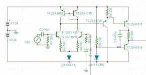
Can you show me please? I'm having trouble picturing your idea. For the attached circuit, the power supply has to be within +/-0.5 volt for good performance. It's like the VAS is balanced on a knife edge, which is not comfortable for me. (this is only for full power output, for much lower output the allowable variation in the power supply is at least twice that)
(T5 actually has it's collector connected to ground, not the -24V supply)
Attachments
Last edited:
With reference to your post #32,
I followed Hephaïstos-Perrot (Lavardin)'s works from the start of the beginning in "L'Audiophile" and then Peufeu's works, often mentionned on this forum, about thermal/memory distorsion.
I found the concept most interesting but the allegated facts were never undoublty demonstrated with standard NFB configurations.
So, last year, I did some real tests to check its existence.
You'll find them here (the text is in french, however there are tables of results which can be understand by anybody) :
Distorsions peu connues des étages d'entrée des amplis
My conclusion is that memory distorsion can't be said to be significative.
Currently, I'm finishing my third stereo Renardson MRJ7 which I am very fond of. Here is a description of the second MRJ7 I made (10 MBytes, in french again but with lot of pictures and a simple test of PSRR) :
L'amplificateur de Mike Renardson à transistors Mosfet | A comme Audio
Small box, small heatsink, small transfo, small caps (4400 µF), but no noise and hum, even when hearing headphones directly connected at the amp output. Because of its high loop gain, the MRJ7 has a high PSRR.
Great work and very good documentation - thank you. Unfortunately I don't speak french and thus I must try to convert the PDF text in MS-word about ABBYY FineReader for the possibility of the Google language tools use.
It would be interesting to know, what happens by connecting of a very large outdoor power supply to your MJR7 with the same voltage values behind the additional used chokes (low DC-impedance air coils like to see about
http://www.diyaudio.com/forums/pass...itional-op-amp-ultimate-sounding-phl1230.html
arround 10mH/0,5 ohms).
I would use capacitor values of approximately 10mF until 20mF between rectifier and air coil and 20mF until 47mF between coil and amp, allocated close by the amp. I use for such projects 4 pcs or 6 pcs 12V lighting transformers (250-500VA each transformer - 1000VA - 3000VA at whole) that looks like this here:
http://img0.billiger.de/a/3269/267965158_L.jpg
My favorite caps for such applications are the follow:
http://www.mundorf.com/deutsch 1.1/kondensatoren2.htm
based on
http://www.ftcap.de/tl_files/ftcap/datenblaetter/elektrolyt/GW2012.pdf
The lighting transformers should be far away from the coils and the MJR7.
check also in this case my post #217 about
http://www.diyaudio.com/forums/solid-state/216409-power-supply-resevoir-size-22.html
Last edited:
Currently, I'm finishing my third stereo Renardson MRJ7 which I am very fond of. Here is a description of the second MRJ7 I made (10 MBytes, in french again but with lot of pictures and a simple test of PSRR) :
L'amplificateur de Mike Renardson à transistors Mosfet | A comme Audio
Small box, small heatsink, small transfo, small caps (4400 µF), but no noise and hum, even when hearing headphones directly connected at the amp output. Because of its high loop gain, the MRJ7 has a high PSRR.
I just finished building an MJR7 MK5 myself. Had been sarching for a single-rail design that could use the 72vdc of the Dynaco SCA-80Q, which I found at a thrift store. The Dynaco's amp is primitive, but it's a nice chassis with a good power transformer, so the MJR7 was a great little DIY project. Really enjoyed Mike's no-nonsense design. He clearly knows his stuff. I've no doubt the amp performs as well as he claims, no way to measure, but my ears are happy.
")
Wish I read French, your analysis looks great.
Here's the board inside the Dynaco, with a heatsink salvaged from an old Sanyo receiver.
An externally hosted image should be here but it was not working when we last tested it.
- Status
- This old topic is closed. If you want to reopen this topic, contact a moderator using the "Report Post" button.
- Home
- Amplifiers
- Solid State
- Best VAS?