i can't find the MJ3001/MJ2501 or an equivalent (MJ2501 Equivalência Transistor ou SMD, MJ3001 Equivalência Transistor ou SMD)... i think that is possible change the final stage, occasionally i have here 2sc5200/2sa1943, and I can found others transistors on old radios/tv/scrap circuits.. any suggestions? thanks
Last edited:
Hello everybody! after work hard for some days, I finished the amp.. by the way, I used TIP142/147 replacing the MJ3001/2501, works great  ...
...
But now I have a problem with preamp... With very low gain, sounds clear, but with local radio on background, and when I put more gain, it emits a high frequency, very loud, very, very, very loud (like: zuimmmmm.)
I'm dissapointed with this preamp, I double checked too... :/
I dont know if i messed up assembling the preamp.. the diagram seems pretty confused, but I think that I did it right... In attachment there is a piece from diagram that explains the "ground" on preamp, I followed that...
Anybody can help? Thank you
...But now I have a problem with preamp... With very low gain, sounds clear, but with local radio on background, and when I put more gain, it emits a high frequency, very loud, very, very, very loud (like: zuimmmmm.)
I'm dissapointed with this preamp, I double checked too... :/
I dont know if i messed up assembling the preamp.. the diagram seems pretty confused, but I think that I did it right... In attachment there is a piece from diagram that explains the "ground" on preamp, I followed that...
Anybody can help?
Thank youAttachments
tip 142-147 will work there but never make it in long run its actually a terrible device ... drop in replacement and as used in later or bigger Marshall is the MJ 11015-16
Edit : as seen from the schematic there is no trimmer to adjust the bias ....Obviously if you replace transistors with something else bias will change and will need to be readjusted often when this is happen we have to replace one of the resistors on the Vbe area with a trimmer .... you need to verify bias according to the schematic cause higher bias will result to higher temperature that heatsink will not manage and eventually will fail and lower bias will increase distortion
Edit : as seen from the schematic there is no trimmer to adjust the bias ....Obviously if you replace transistors with something else bias will change and will need to be readjusted often when this is happen we have to replace one of the resistors on the Vbe area with a trimmer .... you need to verify bias according to the schematic cause higher bias will result to higher temperature that heatsink will not manage and eventually will fail and lower bias will increase distortion
Last edited:
tip 142-147 will work there but never make it in long run its actually a terrible device ... drop in replacement and as used in later or bigger Marshall is the MJ 11015-16
Edit : as seen from the schematic there is no trimmer to adjust the bias ....Obviously if you replace transistors with something else bias will change and will need to be readjusted often when this is happen we have to replace one of the resistors on the Vbe area with a trimmer .... you need to verify bias according to the schematic cause higher bias will result to higher temperature that heatsink will not manage and eventually will fail and lower bias will increase distortion
I checked Vbe (from tip142/147), is about 0.83~0.87 V... I think that is normal... In max volume, the temperature are on 29ºC
...but it seems that it dont have a problem with final output stage... I made a little test here, injecting signal from a external preamp pedal in the C8, and works fine...
Hi
It shows 12mA bias on the diagram. For 12mA bias, you should measure ~4mV across the 0.33R output emitter resistors. Each Darlington has two forward PN junctions, two Vbe's to overcome cutoff. Each device should require 1.1-1.2V in order to conduct bias. So you should see 2.2-2.4V between the bases, or the Vce of transistor 4.
It shows 12mA bias on the diagram. For 12mA bias, you should measure ~4mV across the 0.33R output emitter resistors. Each Darlington has two forward PN junctions, two Vbe's to overcome cutoff. Each device should require 1.1-1.2V in order to conduct bias. So you should see 2.2-2.4V between the bases, or the Vce of transistor 4.
Hi
It shows 12mA bias on the diagram. For 12mA bias, you should measure ~4mV across the 0.33R output emitter resistors. Each Darlington has two forward PN junctions, two Vbe's to overcome cutoff. Each device should require 1.1-1.2V in order to conduct bias. So you should see 2.2-2.4V between the bases, or the Vce of transistor 4.
I got 1.94V on Vce TR4
I put the preamp in a separate pcb now, but the noise keeps popping up ... with low gain in the "VR1" the guitar is clean, but when I raise a little more, a low-frequency noise appears, and more gain I increase, the frequency becomes higher, with a very high volume too, and at some point, when I increase more gain, the noise disappear but the guitar signal disappear too.. I recorded a sample mp3, is attached...
I recorded a sample mp3, is attached...Attachments
Last edited:
It seems like you have marginal stability problems .
Check C13 ...220pf.....this helps keep the power amp stable
Check all the feedback components/wiring around IC1B .
I replaced all components, including the IC.. I checked all circuit comparing with the diagram... And I connected the preamp to the power amp with a microphone wire... I also tested the preamp with separate power supply, same problem ..
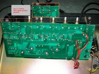
I was looking for another diagram, and I found this photos from a Marshall 3005 Lead 12 SS:


I have noticed many differences between these pictures and the diagram, for example, R2 is 2k2 on amp of the photos, but the diagram it is 33k .. And on the photo, the amp have a bias adjustment, the diagram don't...
Look to the attachment .. I'm seeing right?
I have noticed many differences between these pictures and the diagram, for example, R2 is 2k2 on amp of the photos, but the diagram it is 33k .. And on the photo, the amp have a bias adjustment, the diagram don't...
Look to the attachment .. I'm seeing right?
Attachments
Last edited:
- Status
- This old topic is closed. If you want to reopen this topic, contact a moderator using the "Report Post" button.
- Home
- Live Sound
- Instruments and Amps
- Final output stage amp marshall