Sounds familiar Edmond. Happens to me all the time!
One thing I'm concerned about is reducing the input impedance. With an input capacitance of 2.5nF, a 100k volume pot at center position will result in a 2.5KHz LP filter! This improves to 25KHz with a 10k pot, which may be acceptable depending on who you talk to. C2 can bootstrap the input capacitance but can also make the amp a source-dependent resonator/oscillator. If the LP were moved to before the pot this would be no object, but do you think EMI could be an issue then? The LTP does need a minimal input decoupling cap so stability is not source-dependent. So perhaps very careful input bootstrapping is in order.
One thing I'm concerned about is reducing the input impedance. With an input capacitance of 2.5nF, a 100k volume pot at center position will result in a 2.5KHz LP filter! This improves to 25KHz with a 10k pot, which may be acceptable depending on who you talk to. C2 can bootstrap the input capacitance but can also make the amp a source-dependent resonator/oscillator. If the LP were moved to before the pot this would be no object, but do you think EMI could be an issue then? The LTP does need a minimal input decoupling cap so stability is not source-dependent. So perhaps very careful input bootstrapping is in order.
Sounds familiar Edmond. Happens to me all the time!
One thing I'm concerned about is reducing the input impedance. With an input capacitance of 2.5nF, a 100k volume pot at center position will result in a 2.5KHz LP filter! This improves to 25KHz with a 10k pot, which may be acceptable depending on who you talk to.
C2 can bootstrap the input capacitance but can also make the amp a source-dependent resonator/oscillator. If the LP were moved to before the pot this would be no object, but do you think EMI could be an issue then? The LTP does need a minimal input decoupling cap so stability is not source-dependent. So perhaps very careful input bootstrapping is in order.
Hi Keane,
Putting a pot directly in front of the input filter is asking for troubles. Not only in this particular case, but also with any other power amp equipped with an input filter. As you know, it's well known issue.
I think the best way to circumvent these issues is to use an active volume control, i.e. the volume pot in the feedback path of an op-amp. D. Self has done this, for example. See his 'precision pre-amp', Electronics World, Sept. 1996, pp.708..716. This way you get a sufficient low output impedance (and lower noise!)
Cheers,
E.
Requiring an active volume control however increases the parts count for a build of this amp. Buffering the +- inputs would make the circuit virtually impervious to source impedance. I have not found a way of doing this that doesn't mess up the aesthetic symmetry, but it can be done.
If there is a simple way to bootstrap a 2-pole input filter to reduce input impedance, the next barrier is that off component tolerances can ruin the gains. For instance if we bootstrap an input capacitance of 2.7nF, and the 2 caps have 5% tolerance, we have +-270pF range of input capacitance. Negative capacitance would be absolutely horrifying so we'd want to swamp it with another 270pF cap giving us a final input capacitance range of 0pF-540pF.
With LTP buffers we can solve this problem by using smaller input capacitors. This way with 5% tolerance can can achieve +-27pF input capacitance with a 270pF cap, and add a 33p cap to swamp it and give some margin for error. Now we have an input impedance of say 100k and 6p-60p input capacitance; compatible with any source and tolerant of smaller input caps. No one can complain of the input impedance being too high because you can just short the input with a 10k resistor or so.
I envision this adding 2 extra BJTs and several small passive components. Might be more economical than a whole new board and circuit just for impedance fixes; unless you already planned on a preamp in front for all inputs.
Last edited:
Hi Keane,
> I envision this adding 2 extra BJTs and several small passive components. Might be more economical than a whole new board and circuit just for impedance fixes; unless you already planned on a preamp in front for all inputs.
Why should I fix impedance issues of a pre-amp in the next link of the audio chain, i.e. the power amp? Any decent signal generator is supposed to exhibit a sufficiently low and constant output impedance (50 Ohms or so). IMHO, the same shall apply to pre-amps.
As for volume pots in the FB path, please read this: Bruno Putzeys r4 random rants, raves and ramblings
Cheers,
E.
Return Ratio in the SuperTIS
Hi Edmond
Looks like you are back on the the forum so I hope your PC problems are sorted.
I want to better understand some of your comments on your SuperTIS website.
You mention a few times the need to lower the current gain to keep loop stability. Why the emphasis on current?
The Return Ratio is just a ratio, the same for current or potential.
For instance a cascode can increase the RR even with no current gain, yes?
It seems to me that power gain could be a more useful metric but I have not seen this approach used. I have seen a few references to "non ergic" feedback that seem to imply this perspective but they are a bit obscure.
Don't have a specific question, more just want to clarify my own ideas and learn your perspective.
Best wishes
David
Hi David,
I just scanned my website on 'current gain'. I found it two times, it's about the TIS itself and the current gain is just 1x. I only mentioned this, because it is much much lower than a conventional TIS. But you are right, this is only part of the story, as the power gain is much higher than 1x.
>the need to lower the current gain to keep loop stability
I couldn't find it. Could you tell me where exactly I said that?
/OT
As for my PC, it's on the air again, though not fully completed. The cooling needs a finishing touch, for example. I finally found a heat sink that really makes sense: a Silverstone NT01 pro. Why this one? Well, you can mount it in such a way that the fans are seated between the cooling ribs and the rear of the PC housing. With this arrangement the fans suck cool air from the outside, instead of just circulating warm air inside PC cabinet, as most other fans do.
Also the triple boot system (XP/W7/W8) is not ready yet. I need three OSes to test DiAna. BTW, I also tested a couple of sound cards, a Lynxstudio L22, for example. What a delight! Rather expensive, but worth every penny. At the other side, I also tested some cards from Creative Labs and ASUS (also designed by Creative). Far more distortion and spurious noise. Also the ASIO drivers don't work. The size of the software is enormous and slows down your PC. What a disgusting bloatware. Please don't touch it!
Cheers,
E.
Last edited:
I just scanned my website on 'current gain'. I found it two times, it's about the TIS itself and the current gain is just 1x. I only mentioned this, because it is much much lower than a conventional TIS. But you are right, this is only part of the story, as the power gain is much higher than 1x.
>the need to lower the current gain to keep loop stability
I couldn't find it. Could you tell me where exactly I said that?
I paraphrased, but the sections on Super_TIS.HTML that I meant
To maintain sufficient stability a redistribution of gain stages is required This is done by:
1. Replacing the ubiquitous VAS (with a gain of beta or even beta^2) by a cascode (with a current gain of 1x) which is directly connected to the current mirror,
"VAS... gain" is clearly current gain. So a lower current gain to maintain loop stability.
2. Putting a pre-driver after the cascode, which restores the gain of the whole chain, see fig.3a.
Current gain implied since that is what a pre-driver does.
Although the current gain of the TIS is just 0dB, the gain-bandwidth-product of the stages enclosed by the Miller loop is still too high.
Since the VAS has been replaced by a cascode having a current gain of just 1x,
It should be noticed that the current gain and gm are still rather low.
Therefore, it's highly recommended to compensate for the lack of gain by means of a pre-driver
Current gain implied.
Best wishes
David
Hi David,
Now I understand what you mean Thx.
>You mention a few times the need to lower the current gain to keep loop stability. Why the emphasis on current?
It's a long time ago. Probably because it was easier to manipulate the current gain instead of the voltage gain. Another possibility might be the Tian gain probe showed that it was (mainly) current which determined the RR.
>It seems to me that power gain could be a more useful metric but I have not seen this approach used.
The point is that the available power gain is seldom use (at least AF amps that don't make use of transformers). It's either voltage or current that's transferred from the one stage to the next stage. So I'm not sure whether power is a more useful metric. As for HF and UHF, it's a different story, of course.
Cheers,
E.
Hi Edmund. For months I have been working with my own new computer and haven't has time for much else. It's an AMD FX8350 with an SSD. I'm hoping I won't need to upgrade for a long time. I already had the PSU, case and all peripherals, so I didn't break a leg. I wonder what you got?
Your Diana software is something I think I'd really like to have, but I'm using Linux, exclusively ever since my HD died. Would you be willing to make it fully compatible with Wine? That is what Linux users run windows programs with.
I myself have been working with programming. I'm starting with assembly. It's the only language that doesn't massively confuse me. My latest endeavor:
flat assembler - View topic - Circle gone wrong
I want to try many things, like FFT stuff.
What is the cheapest soundcard you could recommend? A very good friend bought me a Xonar DX; is there something better for the price?
Another possibility might be the Tian gain probe showed that it was (mainly) current which determined the RR.
How does the Tian probe in your simulator show the different contributions of current gain and potential gain to RR? IIRC you don't use LTSpice.
>It seems to me that power gain could be a more useful metric but I have not seen this approach used.
The point is that the available power gain is seldom use (at least AF amps that don't make use of transformers). It's either voltage or current that's transferred from the one stage to the next stage. So I'm not sure whether power is a more useful metric. As for HF and UHF, it's a different story, of course.
I think the references to "non-ergic" feedback used hypothetical transformers to achieve perfect lossless feedback and thus simplify the theory.
They were from Europe, perhaps an analytic technique with some history there. Have you come across it?
The point about power was to emphasize that one could put a transformer in a feedback loop and have any arbitrary current gain but without power gain there is no instability.
Somewhat related is that my search for low capacitance and fast transistors to improve stability has now reached the point that they quote S parameters, usually used for UHF radio transistors. Not very familiar with these, funny that a strictly scientific analysis should exceed the wildest subjectivist claims about "speed"
")
Best wishes
David
Last edited:
To all,
Regarding the circuit as shown below, I like to know whether anyone has seen this front-end before. If so, I'm curious to learn more about it and how it behaves in real life. More details can be found here.
(BTW, I'm still editing and updating that page, so it's not yet finished)
Cheers,
E.
This circuit was essentially done previously by the japanese chap at evolve amplifiers.
/OT
Hi Keane,
Nice to hear from you again. I upgraded my PC about the same way, though with an Intel i-5 3570k CPU (just as fast as a FX8350) and a MSI B75A-G43 motherboard. I'm telling these details, because it might be important to other people who own a (legacy) PCI sound card. Many modern motherboards are equipped with a Z77 chipset, which provides no native support for old fashioned PCI cards. So what's the problem? Many of these motherboard do have PCI slots as well. But... these slots are interfaced via a buggy 3rd party chip (ITE or Asmedia) to a PCI-e lane. This doesn't work with time critical sound cards. You will get dropouts. So just buy PCI-express sound card, problem solved. No! Many professional sound cards (a Lynx L22, for example) still have a PCI bus. So I opted for the B75 chip set (targeted at small businesses), which does support PCI natively.
I'm sorry Keane, you are asking too much. I simply haven't the time to install Linux and Wine and test DiAna under yet another OS. Besides, DiAna isn't finished yet, and it takes already a lot of time to test and debug it under XP, W7, W8 (32 and 64 bits) together with bunch of different sound cards. I also have to write the documentation. Debugging this kind of software takes an awful lot of time. I was confronted for example, with a dropout that happened only once in 5 hours or so. It appeared to be 'race condition'. I solved it with a mutex, but this single bug cost me already 1 week!
Nice, hardcore programming. I like that.
Regarding graphics, I also would do it in assembler (and I did, years ago). For a FFT and that kind of stuff, I would program it in C (not C++, or C#, etc)). Almost just as fast and much easier. Have a look at "Numerical Recipes in C" (http://www.nr.com)
A few month ago I bought a comparable card, a Xonar Essence ST, same brand and designed by the same guys: Creative Labs. Please don't touch it. Everything form Creative is cheap consumer cr@p and their software is the most disgusting bloatware I have ever seen. Their ASIO driver doesn't work, neither with DiAna, nor with other software which needs an ASIO driver.
Actually, there ain't no cheap sound cards which are suitable for measurements. I own an old ESI Waveterminal 192X. It only performs reasonable after I've replaced some op-amps, resistors and capacitors for better ones. From the same brand you might buy an ESI Juli@. Bob Cordell has one. Ask him about his findings (though, at the moment he is very busy!).
If you want to measure distortion in the ppm range, choices get very limited. As a matter of fact, only stuff from Lynxstudio I can take seriously. This was the case ten years ago. Today, odd enough, it's still the case. Regrettably, a Lynx is rather expensive. You might, just as I did, buy a 2nd hand one on ebay.
Hope this info helps.
Cheers,
E.
Hi Edmond. For months I have been working with my own new computer and haven't has time for much else. It's an AMD FX8350 with an SSD. I'm hoping I won't need to upgrade for a long time. I already had the PSU, case and all peripherals, so I didn't break a leg. I wonder what you got?
Hi Keane,
Nice to hear from you again. I upgraded my PC about the same way, though with an Intel i-5 3570k CPU (just as fast as a FX8350) and a MSI B75A-G43 motherboard. I'm telling these details, because it might be important to other people who own a (legacy) PCI sound card. Many modern motherboards are equipped with a Z77 chipset, which provides no native support for old fashioned PCI cards. So what's the problem? Many of these motherboard do have PCI slots as well. But... these slots are interfaced via a buggy 3rd party chip (ITE or Asmedia) to a PCI-e lane. This doesn't work with time critical sound cards. You will get dropouts. So just buy PCI-express sound card, problem solved. No! Many professional sound cards (a Lynx L22, for example) still have a PCI bus. So I opted for the B75 chip set (targeted at small businesses), which does support PCI natively.
Your Diana software is something I think I'd really like to have, but I'm using Linux, exclusively ever since my HD died. Would you be willing to make it fully compatible with Wine? That is what Linux users run windows programs with.
I'm sorry Keane, you are asking too much. I simply haven't the time to install Linux and Wine and test DiAna under yet another OS. Besides, DiAna isn't finished yet, and it takes already a lot of time to test and debug it under XP, W7, W8 (32 and 64 bits) together with bunch of different sound cards. I also have to write the documentation. Debugging this kind of software takes an awful lot of time. I was confronted for example, with a dropout that happened only once in 5 hours or so. It appeared to be 'race condition'. I solved it with a mutex, but this single bug cost me already 1 week!
I myself have been working with programming. I'm starting with assembly. It's the only language that doesn't massively confuse me.
Nice, hardcore programming. I like that.
My latest endeavor:
flat assembler - View topic - Circle gone wrong
I want to try many things, like FFT stuff.
Regarding graphics, I also would do it in assembler (and I did, years ago). For a FFT and that kind of stuff, I would program it in C (not C++, or C#, etc)). Almost just as fast and much easier. Have a look at "Numerical Recipes in C" (http://www.nr.com)
What is the cheapest soundcard you could recommend? A very good friend bought me a Xonar DX; is there something better for the price?
A few month ago I bought a comparable card, a Xonar Essence ST, same brand and designed by the same guys: Creative Labs. Please don't touch it. Everything form Creative is cheap consumer cr@p and their software is the most disgusting bloatware I have ever seen. Their ASIO driver doesn't work, neither with DiAna, nor with other software which needs an ASIO driver.
Actually, there ain't no cheap sound cards which are suitable for measurements. I own an old ESI Waveterminal 192X. It only performs reasonable after I've replaced some op-amps, resistors and capacitors for better ones. From the same brand you might buy an ESI Juli@. Bob Cordell has one. Ask him about his findings (though, at the moment he is very busy!).
If you want to measure distortion in the ppm range, choices get very limited. As a matter of fact, only stuff from Lynxstudio I can take seriously. This was the case ten years ago. Today, odd enough, it's still the case. Regrettably, a Lynx is rather expensive. You might, just as I did, buy a 2nd hand one on ebay.
Hope this info helps.
Cheers,
E.
How does the Tian probe in your simulator show the different contributions of current gain and potential gain to RR? IIRC you don't use LTSpice.
Hi David,
You're an astute man, I like that. Of course it was another probe (home-brew). Sorry for the confusion.
BTW, I'm using MC10.
I think the references to "non-ergic" feedback used hypothetical transformers to achieve perfect lossless feedback and thus simplify the theory.
They were from Europe, perhaps an analytic technique with some history there. Have you come across it?
The point about power was to emphasize that one could put a transformer in a feedback loop and have any arbitrary current gain but without power gain there is no instability.
Somewhat related is that my search for low capacitance and fast transistors to improve stability has now reached the point that they quote S parameters, usually used for UHF radio transistors. Not very familiar with these, funny that a strictly scientific analysis should exceed the wildest subjectivist claims about "speed"
Best wishes
David
Your idea of "non-ergic" feedback is new to me and I have to admit that I can hardly oversee the implications of such a FB arrangement. I'm afraid that my imagination fails short to be of any help in your quest for the ultimate speed. So you have to figure it out by yourself. Sorry.
Cheers,
E.
Your idea of "non-ergic" feedback is new to me and I have to admit that I can hardly oversee the implications of such a FB arrangement.
I don't think it has any implications in practice, only that it simplifies the theory when the feedback is lossless.
It is borrowed from physics and they like to use an "energy" perspective so power is a natural metric.
In fact Return Ratio can be considered as a power metric - RR > 1 means power gain. This is what I implied earlier but I don't think I have ever seen it explicitly stated. Seems I still have a physicist perspective too.
Best wishes
David
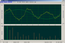
dreaming about specs
The official specs of the Xonar are over-flattered.
The official specs of the L22 are under-flattered.
As for the Xonar, I can't measure right now (as I've sold this card as soon as possible), but regarding the L22, the distortion of the ADC and DAC together at 1kHz is 2ppm. See pic.
The official specs of the Xonar are over-flattered.
The official specs of the L22 are under-flattered.
As for the Xonar, I can't measure right now (as I've sold this card as soon as possible), but regarding the L22, the distortion of the ADC and DAC together at 1kHz is 2ppm. See pic.
Attachments
The truth is grave, as always. On Linux, I have to use open-source drivers developed by independent hobbyists. I wonder if the linux drivers work better? Wine emulates DirectSound and Wave Out; do you use a different interface? I actually discovered while messing around that Wine did better at some sound-related task than when I actually used the original windows library. I think I lost that info when my HD died though.
Researching FFT is frustrating. I get the impression that the basic algorithm is simple, but whenever people write about it they use so much terminology it sounds like another language. I seem to learn more when I just look at the code to see what's going on. A picture is gradually forming in my head though.
Researching FFT is frustrating. I get the impression that the basic algorithm is simple, but whenever people write about it they use so much terminology it sounds like another language. I seem to learn more when I just look at the code to see what's going on. A picture is gradually forming in my head though.
- Status
- This old topic is closed. If you want to reopen this topic, contact a moderator using the "Report Post" button.
- Home
- Amplifiers
- Solid State
- Has anyone seen this front-end before?