Ill need some software to convert pdf pages to image files first so Ill need a day or two as Ive been planning to purchase said software for a while anyhow.
No need to purchase anything! The free version of PDF-XChange viewer will do this for free (assuming you're using Windows; in OS X the bundled Preview can also do this).
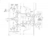
Here are the schematics. I was wrong about the manufacturing date though, got some more info via Pioneer, the first amps sold using this outputstage was in 1982. Note their are six pairs of LAPT output transistors driven by this stage which are not shown.
Attachments
Last edited:
Thanks homemodder, much appreciated.
I note earlier you said:
Presumably you are talking Q25+Q27? Device capacitances depend upon voltage across the relevant junction rather than current flow, here the relevant junction is c-b. So, placing two identical devices in parallel will give you slightly under double the capacitance, not lower capacitance. (current per device will be halved; Vbe will therefore be lower for a given standing current, very slightly increasing the c-b voltage drop and reducing an individual transistor's Ccb; however, now there's two transistors in parallel and capacitors in parallel add.)
I note earlier you said:
The driver is composed of two transistors in parralell to achieve higher bandwith and lower device capacitances at optimal bias point.
Presumably you are talking Q25+Q27? Device capacitances depend upon voltage across the relevant junction rather than current flow, here the relevant junction is c-b. So, placing two identical devices in parallel will give you slightly under double the capacitance, not lower capacitance. (current per device will be halved; Vbe will therefore be lower for a given standing current, very slightly increasing the c-b voltage drop and reducing an individual transistor's Ccb; however, now there's two transistors in parallel and capacitors in parallel add.)
Maybe I shoud have explained, two devices used in parralell instead of one device for the same SOA. The advantage is that two lower Ic capable devices have much lower capacitances even when used in parallel than a higher Ic capable part and then their is also the advantage of FT. Compare the device capacitances of say of two 2sa1837 in parrallel to 1 onsemi mje1503xx series driver. When using transistors as emitter followers I find the Cbe of much more importance than Ccb.
Maybe I shoud have explained, two devices used in parralell instead of one device for the same SOA.
Ah, ok.
The advantage is that two lower Ic capable devices have much lower capacitances even when used in parallel than a higher Ic capable part and then their is also the advantage of FT.
Sadly many high-voltage, high-Ft, ultra-low capacitance BJTs have been discontinued by their respective manufacturers (mostly Sanyo (now ON) and Fairchild)
 As far as I can tell this is because their main market was actually CRT televisions.
Compare the device capacitances of say of two 2sa1837 in parrallel to 1 onsemi mje1503xx series driver.
I don't like ON's drivers. I don't understand why, when they can make the excellent 3281/1302 etc. output transistors, they don't also make something more like the 2SC5171/2SA1930 from Toshiba as drivers. Alarmingly, these Toshiba parts have become NRND (Not Recommended For New Designs), which in turn will become "obsolete" soon. Apparently they are working on replacements though, so fingers crossed! (the 2SA1837/2SC4793 are also NRND).
When using transistors as emitter followers I find the Cbe of much more importance than Ccb.
Really? When operating in common-collector, a BJT's Cbe is effectively bootstrapped due to Vbe being more-or-less constant. Cbe shouldn't have much of an effect.
"Sadly many high-voltage, high-Ft, ultra-low capacitance BJTs have been discontinued by their respective manufacturers (mostly Sanyo (now ON) and Fairchild) As far as I can tell this is because their main market was actually CRT televisions."
This will be a real pain for high power design. We will be left itch running TIS stages at very low Iq (so we can use small ignal devices), or MOSFET based solutions.
This will be a real pain for high power design. We will be left itch running TIS stages at very low Iq (so we can use small ignal devices), or MOSFET based solutions.
This will be a real pain for high power design. We will be left itch running TIS stages at very low Iq (so we can use small ignal devices), or MOSFET based solutions.
I know! MOSFETs would be OK but of course require higher voltage rails due to high threshold voltage and low gm.
If I was insanely rich I'd get a manufacturer to resurrect some of these obsolete BJTs.
What do you think about this OPS?
Looks interesting. Q3 and Q4 have low Vce drops so you can use much faster transistors such as the 2SC5707/2SA2040 (ten times the Ft of the MJEs). If you download my zip file of transistor models, I have all the data necessary to build models of these transistors but I haven't had the chance to develop the models yet.
How's this for a crazy idea?
Use current-feedback op-amps as high-input-impedance "transistors". This requires a floating supply for the op-amps which I've shown driven from the amplifier output. I'm concerned this may cause stability issues (at HF the power supply pins of the op-amps become additional signal inputs so there's a feedback path from amplifier output to the op-amp outputs). Solving this would require driving the floating supply from another amplifier, but this could be a very simple amplifier. Non-linear distortion performance of this second amp wouldn't really matter, but it would have to have a flat frequency response, like the main amplifier.
I've drawn an output stage with cascoded output transistors, allowing use of the aforementioned 2SC5707/2SA2040.
Here's the schematic. The references to Q10 and Q11 collectors refer back to Edmond's schematic in the first post of this thread.
Sadly many high-voltage, high-Ft, ultra-low capacitance BJTs have been discontinued by their respective manufacturers...
I don't like ON's drivers. I don't understand why, when they can make the excellent 3281/1302 etc. output transistors, they don't also make something more like the 2SC5171/2SA1930 from Toshiba as drivers. Alarmingly, these Toshiba parts have become NRND (Not Recommended For New Designs), which in turn will become "obsolete" soon. Apparently they are working on replacements though, so fingers crossed! (the 2SA1837/2SC4793 are also NRND).
Like the Toshiba but without the pathetic SOA when you crank up the volts.
I know there is a trade-off but I think you are correct, the overall performance of the 4281/4302 is excellent why not a comparable driver?
What is the story on the Toshiba replacements?
I stocked up on 4281/4302 when they were discontinued, should I stock up on drivers - is there a better option than 2SC5171/2SA1930?
And thanks for the ASC a day or so back.
Have not had a chance to do much yet.
Best wishes
David.
Like the Toshiba but without the pathetic SOA when you crank up the volts.
Yes, the SOA is a bit of an issue on those parts. Still, the capacitance is so low that using two in parallel shouldn't slow things down much.
What is the story on the Toshiba replacements?
All I know is that if you look at Toshiba's latest BJT catalogue, it lists some transistors with suitable ratings (160V/1.5A and 230V/1A) in TO126 packages as "being planned".
should I stock up on drivers - is there a better option than 2SC5171/2SA1930?
The Fairchild KSA1220A/KSC2690A have similar performance. The SOA is better, but both parts have slightly lower Ft and the NPN part doesn't have a flat beta vs. Ic characteristic. Both Fairchild and Toshiba parts are available from Mouser at reasonable prices.
And thanks for the ASC a day or so back.
Have not had a chance to do much yet.
You're welcome.
Here's another output stage with op-amp-based drivers. Anyone seen anything like this done before?
Drivers
The recommended "replacements" have lower maximum current and lower Vceo in a smaller format so presumably even worse SOA. Maybe time to stock up a little.
Thanks for the heads up.
Best wishes
David
... if you look at Toshiba's latest BJT catalogue, it lists some transistors with suitable ratings (160V/1.5A and 230V/1A) in TO126 packages as "being planned".
The recommended "replacements" have lower maximum current and lower Vceo in a smaller format so presumably even worse SOA. Maybe time to stock up a little.
Thanks for the heads up.
Best wishes
David
Harry:
The floating supply ground ill have significant capacitance to ground from the amp output no? This ill need to be considered for stability reasons. Furthermore the large surface area of the transformer and hatnot could radiate statically quite a bit.
The MJE253/243 are comparable to or better than the C4793/A1837. Furthermore, if e just get a bit more comfortable ith paralleling drivers, e ill preserve Ft ithout sacrificing it for higher poer. This is based on the datasheets and Cordell's SPICE models.
Cbe is VERY important! It basically determines the speed limit for practical usage of any given BJT. There are some seemingly nice lo-Ccb BJT's that have monstrous Cbe and therefore are useless. Cbe is hat caused the slo-rising slope of Ft ith Ic. It is also hy the KSC1220/C2690A are not very useful at 10mA. BJT's ith less Cbe generally increase the stability margins, and therefore useful bandidth, of any amplifier they are used in.
Cbc can be cascoded out or compensated for, but there is usually no ay to fix the inherent speed limit caused by Cbe. If the driver stage of a BJT EF amp is made poerful enough to deal ith Cbc, Cbe then becomes the limit on the stage's bandidth. It can be increased slightly by hanging capacitors about 5xCbe off of the output, hich allo quicker charge/discharge through Cbe. But only slightly, and it results in a steeper negative bandidth slope. Furthermore the Cbe of output BJT's is usually monstrous, hich results in 15-20nF necessary, and this makes stability in a global feedback design problematic. So basically - use the outputs ith the least Cbe, hich are at the moment the ONSemi outputs (they are not all the same). Look for Ft at 100mA, try to go above 20MHz. I prefer my small signal transistors to have at least 100MHz at 1mA.
I think the reason the TIS has such lo distortion itself is because it is basically the most linear a BJT input stage of it's type can be. Therefore, even if input-feedback differential is significantly large, it is still a largely undistorted reproduction of the output currents - IE high open-loop linearity.
hat gets me is that no one is trying to reduce the voltage distortion of the output stage; e can and already have increased input impedance beyond insignificance but the voltage distortion is still as large as it alays as back to the original double EF.
Dadod:
Instead of 10k resistors to the rails, feed the diamond pair ith resistors across the Vbe of Q3 and Q4. This ill increase the input impedance greatly.
Furthermore, you can cascode the BC5xx pair by putting a diode beteen the CCS and the driver emitters, and connecting the BC5xx collectors beteen the CCS and diode. After this both your input resistance and capacitance ill be greatly reduced. To diodes may be better, but may not because the BC5xx series has such great lo-Vce handling ability (but the BC327-25/BC337-25 are still better in this area).
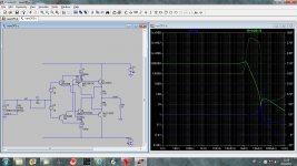
Do you mean like this? Still the same input resistance and a nasty peak at 20 MHz, distortion a bit higher.
dado
Attachments
Dadod:
If those are ideal diode models, check they actually have .68V breakover.
The resonance peaks kind of go ith multi-cascode output stages, because cascoding adds positive feedback paths. For one thing, those bulky MJE1503x drivers are super-overpoered. They ill never sink more than 100mA, and never see a Vce over .6V. Problem: overpoered BJT's have bad lo-Vce behavior. In this position these drivers ill have huge parasitic capacitance and possible Vcesat glitches.
Find some higher-performance drivers. The 2SC4793/A1837 ould be great, so ould the MJE253/243. They ill only dissipate 200m, so you could perhaps even use some TO92's here, as long as they are fast and linear to 100mA.
After you have better drivers, see hat the resonance is like and e can probably do something about it.
The distortion ill alays be bad because you are measuring voltage distortion. There is not much you can do about that ithout using a different circuit. A more meaningful measure of distortion for your circuit ould be input current distortion.
Andre:
Not sure hat you mean about the alt numbers. Ho do you do this?
The BJT tests ere only to help me get a sense of scale; I agree they're not very useful. They performed their function ell didn't they?
Last edited:
- Status
- This old topic is closed. If you want to reopen this topic, contact a moderator using the "Report Post" button.
- Home
- Amplifiers
- Solid State
- Has anyone seen this front-end before?