* of course this is easy for me to say that because I have 24/7 access at work so I don't need to invest anything!
I could tell!
Just not sure yet whether a $400 desolder station is really an investment when I have a manual solder sucker that is OK.I am happy to pay for professional stuff when necessary (people ask why I have a tool-room lathe and a turret mill
)Best wishes
David
Hello Dave,
This desoldering station is cheaper here. These guys are good to deal with.
Now only $300 plus delivery! Which is probably about $100 more! (Why is delivery from the USA usually so expensive? When it is closer than Britain?).
Seriously, thanks for the link. They look to have lots of other useful stuff.
BTW For my last off topic comment of the day - Where are you in OZ?
Best wishes
David
Last edited:
a manual solder sucker
I have only successfully desoldered a through-hole plated board with a manual solder sucker where the device pins are much smaller than the holes. If they're a proper fit, forget it; you can't get a tight fit for the solder sucker tip at the same time as heating the joint. The only way to achieve that is with a desoldering iron.
post918 is referring to post916, Cherry's example layout................ I am not sure what PCB layout you are talking about, there is double side one and single side one...............
I have only successfully desoldered a through-hole plated board with a manual solder sucker where the device pins are much smaller than the holes. If they're a proper fit, forget it; you can't get a tight fit for the solder sucker tip at the same time as heating the joint. The only way to achieve that is with a desoldering iron.
I realized it would be easier to manipulate just the one tool but have not actually tried one so thanks for the advice. It is possible to buy irons with a manual solder sucker built in. These are cheap and appear extract thru the tip just like a power desolder tool, just not continuously. Seem like a reasonable compromise, have you (or anyone else here) tried these?
Best wishes
David
post918 is referring to post916, Cherry's example layout.
I agree with you, I don't understand whay that part of Cherry layout is on the left side.
Super-TIS + BJT-OPS
Hi David,
You will need at least a triplet. Don't forget that the super TIS has one gain stage less than a conventional front end. So you need a pre-driver to compensate for the lack of (current) gain anyhow. But even with a conventional front end, a triplet is recommended. That means that using the super TIS instead, you will probably need a quartet. (Oh, and don't forget to bootstrap the collectors of the pre-driver)
Now the question raises has anyone built a quartet OPS and how difficult it is to tame such an OPS?
Cheers,
E.
I was concerned because I plan to use a BJT OPS and way back at Post #104 you said the front end was not really suitable for that. Presumably the difference between the linear load of 100k and the non-linear load from a BJT triple.
I have considered a BJT triple with a diamond buffer and will sim that at some point.
Best wishes
David
Hi David,
You will need at least a triplet. Don't forget that the super TIS has one gain stage less than a conventional front end. So you need a pre-driver to compensate for the lack of (current) gain anyhow. But even with a conventional front end, a triplet is recommended. That means that using the super TIS instead, you will probably need a quartet. (Oh, and don't forget to bootstrap the collectors of the pre-driver)
Now the question raises has anyone built a quartet OPS and how difficult it is to tame such an OPS?
Cheers,
E.
It is possible to buy irons with a manual solder sucker built in. These are cheap and appear extract thru the tip just like a power desolder tool, just not continuously. Seem like a reasonable compromise, have you (or anyone else here) tried these?
No, I've never tried them. I would imagine they would require a decent PCB clamp; with an active pump desoldering iron I hold the board with one hand and operate the iron with the other hand. You need two hands to operate a manual desoldering iron: one to hold the iron and the other to operate the pump.
Hi David,
You will need at least a triplet. Don't forget that the super TIS has one gain stage less than a conventional front end. So you need a pre-driver to compensate for the lack of (current) gain anyhow. But even with a conventional front end, a triplet is recommended. That means that using the super TIS instead, you will probably need a quartet. (Oh, and don't forget to bootstrap the collectors of the pre-driver)
Now the question raises has anyone built a quartet OPS and how difficult it is to tame such an OPS?
Cheers,
E.
Edmond, I note that you mentioned that loading the front end with 100 k you still get under 1 ppm distortion.
Using a triple output stage, the front end will see a high impedance load (well in excess of 100 k especially if a diamond buffer is used as the first two stages of the triple), but this will be a non-linear impedance even when using nice sustained-beta transistors. If when you connect a triple output stage, you also connect a 100 k resistor to ground, does this help to make the load on the front end look more linear?
Hi Harry,
>a 100 k resistor to ground, does this help to make the load on the front end look more linear?
At first glance I don't think so. Admittedly, the relative nonlinearity will be less, but it's the absolute value of the nonlinear load currents that counts. IOW, adding a linear load doesn't reduce the nonlinear load.
Cheers,
E.
You will need at least a triplet...
Yes, I meant a triplet as the minimal OPS.
In particular I planned a CFP + EF triplet.
But a sim of a triple EF OPS was a bit of a disappointment so perhaps a triple is insufficient. So I want to sim a diamond buffer ahead of a CFP + EF. Could be called a quad or a buffered triple. Sorry if that was not clear.
My concern is because the simplicity of the super TIS is less attractive if there is a compensatory increase in the complexity of the OPS.
A Super TIS variant that tolerates low impedance sufficiently to work well with a triple OPS would be the best of both worlds. But not easy to find so far!
Best wishes
David
David, what output transistors and models did you use for your sim? Presumably you get similar sim results as Edmond for the front-end stand alone. Any reason you wanted to use a CFP+EF triple rather than a diamond buffer + EF triple?
It was not my sim. Arthur did it back at post #103 and Edmond replied that it was consistent with his own results so I did not repeat it.
A CFP + EF looks to be a desirable for bias thermal stability. The EF can be thermal trak with excellent speed and accuracy of bias stability. The driver bias variation is servo-ed out by the CFP and the pre-driver has very little variation in power dissipation and is a TO-126 that can be easily bolted to another TO-126 for ambient correction. Also there is a theoretical benefit to use a CFP (that is a small loop) rather than 2 cascaded loops (to consider the EF as a little -ve feedback loop). A simple form of nested loops in other words.
Best wishes and off to bed for me now
David
It was not my sim. Arthur did it back at post #103 and Edmond replied that it was consistent with his own results so I did not repeat it.
Ah, ok. What I see in that post is what I meant by a diamond buffer + EF triple (as what I mean is [diamond buffer + EF] triple, rather than [diamond buffer] + [EF triple]). Arthur, where did your transistor models come from? Many are really poor. If the models for the drivers aren't great, how about trying my 2SC5171/2SA1930 models? And for the final output devices, I wonder if using 1302/3281 output transistors would make much difference as these have flatter beta vs. Ic, and higher Vceo with possibly correspondingly lower early effect (although this doesn't always go hand-in-hand).
Also there is a theoretical benefit to use a CFP (that is a small loop) rather than 2 cascaded loops (to consider the EF as a little -ve feedback loop).
I don't really like CFPs. I've never made one that didn't suffer parasitic oscillation under some conditions (although this was a very long time ago and possibly things I've learnt since then in terms of layout etc. would help here), they are slow (excess phase kicks in at much lower frequency than with an EF) and whilst there is the tight negative feedback loop, this linearises each half (+ve/-ve) separately and you still have issues with crossover distortion; the crossover is very "sharp" and produces lots of high-order harmonics. Really I'd only consider a CFP operating in class-A and I don't like the corresponding quiescent power dissipation.
PCB Layout
Maybe here some of skilled layout designers could take a challenge and suggest good layout for this amp: http://www.diyaudio.com/forums/solid-state/216780-tt-amp-200w-8ohm-701w-2ohm-7.html#post3165994 according ongoing discurion.
Damir
Maybe here some of skilled layout designers could take a challenge and suggest good layout for this amp: http://www.diyaudio.com/forums/solid-state/216780-tt-amp-200w-8ohm-701w-2ohm-7.html#post3165994 according ongoing discurion.
Damir
Ho much matching do you think is necessary for this frontend? I just measured 10 Fairchild BC550C's. They ere mostly ithin .3mV of each other, but never larger than .8mV apart. In the simulator I find a 2.7mV mismatch causes a 10% current difference in an LTP and a .3mV difference causes a 1.1% current difference.
hich is more important for 2nd harmonic cancellation, matched Ic or matched Vbe? For instance, is Gm dependent on Ic and independent of Vbe? Or, if I have Vbe mismatched transistors, can I intentionally mismatch Ic in order to match Gm and cancel the 2nd harmonic? The simulator is telling me even different transistors ill cancel if just the Ic is kept matched. So I'm guessing Gm is dependent on Ic and independent of Vbe. So for input stages, it seems matching is not as useful if you're not using a (matched) current mirror. And it is seeming that Ic matching has to be ithin 6uA to loer the 2nd harmonic belo the 3rd. This ould seem to require better matching than .3mV, hich ill be somehat tedious...
hich is more important for 2nd harmonic cancellation, matched Ic or matched Vbe? For instance, is Gm dependent on Ic and independent of Vbe? Or, if I have Vbe mismatched transistors, can I intentionally mismatch Ic in order to match Gm and cancel the 2nd harmonic? The simulator is telling me even different transistors ill cancel if just the Ic is kept matched. So I'm guessing Gm is dependent on Ic and independent of Vbe. So for input stages, it seems matching is not as useful if you're not using a (matched) current mirror. And it is seeming that Ic matching has to be ithin 6uA to loer the 2nd harmonic belo the 3rd. This ould seem to require better matching than .3mV, hich ill be somehat tedious...
Ah, ok. What I see in that post is what I meant by a diamond buffer + EF triple (as what I mean is [diamond buffer + EF] triple, rather than [diamond buffer] + [EF triple])
I worked out what you meant. I would call that "a diamond buffer EF triple" as opposed to a "diamond buffer + EF triple" but I like your new notation. Would have saved the uncertainty between Edmond and myself.
I don't really like CFPs. I've never made one that didn't suffer parasitic oscillation under some conditions (although this was a very long time ago and possibly things I've learnt since then in terms of layout etc. would help here), they are slow (excess phase kicks in at much lower frequency than with an EF) and whilst there is the tight negative feedback loop, this linearises each half (+ve/-ve) separately and you still have issues with crossover distortion; the crossover is very "sharp" and produces lots of high-order harmonics. Really I'd only consider a CFP operating in class-A and I don't like the corresponding quiescent power dissipation.
Yes, completely concur that the linearization of each half separately and resultant sharp crossover makes the CFP undesirable as an output.
But as a pre-driver + driver to an EF then the CFP is effectively in class A so the linearization is a benefit. And there is a minor improvement in headroom and efficiency from less volt drop as well as the previously mentioned thermal stability benefit.
So it seems to retain the best points of a CFP that D. Self touts and avoid all the problems that Bob Cordell cautions.
Well, perhaps not all the problems. I am concerned about parasitic oscillations, of course. I have seen many trial and error recommendations but little analysis and optimization. Do you have any analyses that you can recommend?
You say "they are slow". Not sure I follow. If we consider this as a feedback problem then I think we should be able to do better or at least as well as two separate loops. Can we use TMC in a CFP? I already satisfy Self, Cordell and AndrewT and now Edmond will like it too
Best wishes
David
Last edited:
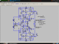
Dave, in my high-current K-multipliers I have had success ith shunt compensation. An L/R could probably be used helpfully but I did not ant to radiate. The idea is to use degeneration to limit Gm hen current is high, so that the Ft's of the transistors are more consistent and thus more responsive to hichever compensation you choose. Bummer, I kno. But it orks best out of anything I have tried in simulation, and is also still nicely fast.
Because of the high currents involved, usually large film capacitors ould be needed to stabilize a CFP any other ay, and these ould ruin distortion, sitching behavior, input impedance, speed and so on. L/R combos might be more useful but again there is the radiation issue.
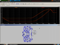
Upper pair curves are output impedance, loer curves are line rejection. Another important thing about this compensation is that it has minimal impact on line rejection.
It is important to note that the CFP output stage has a "distended" tempco. This is because the Vbe and Hfe tempco of the outputs is mirrored in the Vbe of the drivers, in addition to their tempco. If e define tempco in "diode" units, e find that this gives us a fractional tempco, hich means thermal compensation may be very difficult to achieve ithout over or under compensating. This is problematic because e certainly don't ant thermal runaay and e also don't ant our bias to creep don and cause nasty sitching. There be beasts in the ater.
Because of the high currents involved, usually large film capacitors ould be needed to stabilize a CFP any other ay, and these ould ruin distortion, sitching behavior, input impedance, speed and so on. L/R combos might be more useful but again there is the radiation issue.
Upper pair curves are output impedance, loer curves are line rejection. Another important thing about this compensation is that it has minimal impact on line rejection.
It is important to note that the CFP output stage has a "distended" tempco. This is because the Vbe and Hfe tempco of the outputs is mirrored in the Vbe of the drivers, in addition to their tempco. If e define tempco in "diode" units, e find that this gives us a fractional tempco, hich means thermal compensation may be very difficult to achieve ithout over or under compensating. This is problematic because e certainly don't ant thermal runaay and e also don't ant our bias to creep don and cause nasty sitching. There be beasts in the ater.
Attachments
- Status
- This old topic is closed. If you want to reopen this topic, contact a moderator using the "Report Post" button.
- Home
- Amplifiers
- Solid State
- Has anyone seen this front-end before?