In addition, I've changed the frequency compensation of the OPS to a 2nd order
The loop around the OPS (Fig 12c) showed conditional stability. You have moved to second order to improve the stability?
Also curious about Fig 7. Why the low frequency roll-off?
And a last one for today - in Fig. 12 C22 and C23 could be combined and tied to point OPSIP in a natural way. Any reason to use 2 capacitors?
Best wishes.
David
BTW in Dutch we say: 'voor de kat z'n kut' In polite conversation?
")
compensation details
At the same time time I've increased the time-constants of the OPS compensation somewhat. As a result, the PM is about the same, while the distortion is decreased by ca. 40%. Notice that this kind of compensation differs from Miller or TMC. Should we call it 'feed-forward compensation' (comparable to the compensation in Bob's HEC-OPS)?
RC5 and CC5 define the second order response, but at the same time CC5 also provides some phase lead.
What you see there is the local loop gain of the Miller compensation (the lower the frequency, the higher the impedance of the Miller caps, the lower the loop gain, hence...).
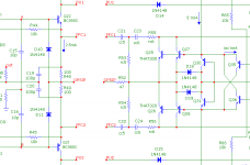
The intention here is that the Miller caps (C19 & C20, see pic below) are directly connected to the output of the TIS buffers, i.e. to the emitters of Q21 respectively Q22. Tying them somewhere in the middle of the OPS compensation network is not a good idea.
(literally: 'for the cat his cυnt')
In the presence of our queen, I wouldn't use those words.
The loop around the OPS (Fig 12c) showed conditional stability. You have moved to second order to improve the stability?
At the same time time I've increased the time-constants of the OPS compensation somewhat. As a result, the PM is about the same, while the distortion is decreased by ca. 40%. Notice that this kind of compensation differs from Miller or TMC. Should we call it 'feed-forward compensation' (comparable to the compensation in Bob's HEC-OPS)?
RC5 and CC5 define the second order response, but at the same time CC5 also provides some phase lead.
Also curious about Fig 7. Why the low frequency roll-off?
What you see there is the local loop gain of the Miller compensation (the lower the frequency, the higher the impedance of the Miller caps, the lower the loop gain, hence...).
And a last one for today - in Fig. 12 C22 and C23 could be combined and tied to point OPSIP in a natural way. Any reason to use 2 capacitors?
The intention here is that the Miller caps (C19 & C20, see pic below) are directly connected to the output of the TIS buffers, i.e. to the emitters of Q21 respectively Q22. Tying them somewhere in the middle of the OPS compensation network is not a good idea.
Best wishes.
David
BTW in Dutch we say: 'voor de kat z'n kut' In polite conversation?
(literally: 'for the cat his cυnt')
In the presence of our queen, I wouldn't use those words.
Attachments
nl.mouser.com? Just looked and they have a reasonable selection in your stated power and resistance range. I guess it depends what you mean by "reasonably priced"; I find these low-ohm power SMT resistors to be surprisingly expensive (i.e. I spend more on Re resistors than I do on output transistors!)
To all,
BTW, does anybody know where to buy reasonably priced low inductive 5W SMT resistors between 0.2 and 0.3 ohm (preferable 0.22 ohm)?
Cheers,
E.
Hello Edmond,
Are you going to use metal oxide types.
Regards
Arthur
But I also need them as current sense resistors.
Hello Edmond,
I did test These and are very promising,
BTW, did You found the solution with the PCB soft already?
Cheers
To all,
BTW, does anybody know where to buy reasonably priced low inductive 5W SMT resistors between 0.2 and 0.3 ohm (preferable 0.22 ohm)?
Cheers,
E.
How about 5 smd ONE ohm ONE watt resistors in parallel of the 1812 smd type or larger.
But I also need them as current sense resistors.
Edmond, is this for protection or are you needing to sense the current for feedback?
That was to be expected...
Never mind , laterals are friendly devices , the current is in proportion of Vgd ,
wich vary at a 1V/A/Device rate or so (Gm = 1S) , just take the sensing point before the gate resistor.
Sure, but I've already bought a bunch of verticals.
If I had accurate models of laterals, maybe I would have go for laterals.
Hello Edmond,
Are you going to use metal oxide types.
Regards
Arthur
Hi Arthur,
No. Just metal film or metal plate.
Cheers,
E.
Hello Edmond,
I did test These and are very promising,
BTW, did You found the solution with the PCB soft already?
Cheers
Hi Smiley,
That were precisely the resistors that I was looking at, but at Farnell they are rather expensive: 3 euro incl. VAT.
Buerklin asks 2 euro, incl. VAT and shipment. That's more reasonable (though still a bit expensive).
Thanks for the hint!
>did You found the solution with the PCB soft already?
At the moment I'm playing with FreePCB and with the translation (export) from MicroCap to this PCB software.
It took me awhile to figure out how to do that. The trouble was how to specify a package of a capacitor and a resistor in MicroCap. The weird thing is that if you haven't first defined a (dummy) spice model for these components, exporting to PCB doesn't work, that is, the package definition is ignored.
Another concern is back-annotation, which is simply not possible.
Cheers,
E.
Last edited:
That was my first solution.How about 5 smd ONE ohm ONE watt resistors in parallel of the 1812 smd type or larger.
Since using 5 smd's is also a bit expensive and not the most elegant solution, I'm also looking for a single resistor alternative.Edmond, is this for protection or are you needing to sense the current for feedback?
Hi Andrew,
Both. Actually, the purpose is threefold:
- Equalizing Id (ballast resistor)
- Protection (current limiting)
- Auto bias (current sensing)
Cheers,
E.
Hi Arthur,
No. Just metal film or metal plate.
Cheers,
E.
Hello Edmond,
Unless you use a special metal film types (ones that fail open circuit) they can burn your PCB when they fail. MOX types fail open and have low inductance also that's why I use them.
Are you using Pads for your PCB layout software.
Regards
Arthur
- Status
- This old topic is closed. If you want to reopen this topic, contact a moderator using the "Report Post" button.
- Home
- Amplifiers
- Solid State
- Has anyone seen this front-end before?