Hi OS,
>"Is there some other aspect I may be overlooking in performance ?"
Yes, there are a few essential aspects:
1. Input inclusive compensation (MIC).
2. Using pre-drivers, because the current gain of the TIS is just unity.
For utmost performance, it is also recommended that the collectors of the pre-driver are bootstrapped, see fig. 6 or 17 of my web page, because the TIS output is very sensitive to a nonlinear (capacitive) loading. As you certainly know, Cob vs Vce is far from linear.
Cheers, E.
I will look into it ... the "TIS" will be the next IPS after the IC based one.
Thanks ! PS - I loiter at your site (and syn08's) often.

OS
With Edmund's circuit you don't have all the gain of a beta-enhanced circuit, so you have to make up for it by using an extra EF stage (predrivers). After you buffer so much the main load on the input stage becomes the capacitance and C-B leakage of the predrivers rather than the currents from the output stage. Cascoding them neatly solves both of these problems. Bootstrapping works alternatively, but not as well.
The merit of Edmund's circuit is not necessarily that it will make your amp distortion-free, but more that it's capable of extremely low distortion when you optimize the application. It has a high "linearity ceiling".
The merit of Edmund's circuit is not necessarily that it will make your amp distortion-free, but more that it's capable of extremely low distortion when you optimize the application. It has a high "linearity ceiling".
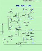
So the last EF in Fig. 6 http://home.tiscali.nl/data.odyssey/Super_TIS.html
makes up the gain.
And TMC is added there , too. I'll try both the cascode and the bootstrapping.
I'm at 16 (or)18 devices , "villagers" don't like many more than that for a
input stage. Hopefully , I can find a compromise between complexity and
sub PPM 20K performance. I'll also have to fit it on a 76 X 102mm PCB.
OS
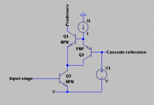
Another thought ... since I will be using an EF buffer - I can run the whole
"core" of the TIS at reduced currents (2.5-3ma).
Then I can use all to-92 (either 992/1845's and Ksp92/42 for Q16/17).
And 3503/1381 300V devices for the predrivers to attach to my EF3 (5.5ma).
This might be "doable".
OS
"core" of the TIS at reduced currents (2.5-3ma).
Then I can use all to-92 (either 992/1845's and Ksp92/42 for Q16/17).
And 3503/1381 300V devices for the predrivers to attach to my EF3 (5.5ma).
This might be "doable".
OS
OS, IMHO do the best you can without worrying about number of devices and or board size...the villagers can Muntz the circuit all they like and SMD will let you put the circuit on a postage stamp if need be. Give it your best of the best. Damn the torpedoes or flak full speed ahead and let the ears be blessed. Best then Muntz it.
OS, IMHO do the best you can without worrying about number of devices and or board size...the villagers can Muntz the circuit all they like and SMD will let you put the circuit on a postage stamp if need be. Give it your best of the best. Damn the torpedoes or flak full speed ahead and let the ears be blessed. Best then Muntz it.
It has many less resistors than the "spooky".
18 semi's + <30 resistors + 14 caps + 4 diodes.
I like how Edmund unifies the reference string for the CCS/cascode -
lower parts count.
OS
Hi OS,
Above url will be invalid per 1-1-2015. Please use my new url: data-odyssey.nl instead.
Cheers, E.
So the last EF in Fig. 6 http://home.tiscali.nl/data.odyssey/Super_TIS.html
Above url will be invalid per 1-1-2015. Please use my new url: data-odyssey.nl instead.
Yes! Therefore you can't omit it. Even in combination with Bob's HEC OPS, which has a rather high input impedance, it was necessary to add this pre-driver (EF) stage (see fig.17). Without this stage, the distortion was higher than Bob's original circuit.makes up the gain.
Normally, sub ppm distortion will always cost a lot of extra trannies (no free lunch). The Super TIS is in this respect not that extreme: 'only' 18 trannies were needed, compared with Bob's front-end: 19 trannies, PGP front-end 36 trannies and a fully complementary design of my with CMCL (fig.9) 28 trannies.And TMC is added there , too. I'll try both the cascode and the bootstrapping.
I'm at 16 (or)18 devices , "villagers" don't like many more than that for a
input stage. Hopefully , I can find a compromise between complexity and
sub PPM 20K performance. I'll also have to fit it on a 76 X 102mm PCB.
OS
Cheers, E.
Any problem running TIS without cascodes and at a lower current ?
I simulated with/without the LTP cascodes , even varied the input Z. THD/
slew/PM-OLG remains nearly the same.
I want all to-92 for the TIS "core" (below). Then I can use some quality
low Cob to-126's for the pre-drivers.
This front ends slew rate is "off the chart" (better than most CFA IPS's).
OS
I simulated with/without the LTP cascodes , even varied the input Z. THD/
slew/PM-OLG remains nearly the same.
I want all to-92 for the TIS "core" (below). Then I can use some quality
low Cob to-126's for the pre-drivers.
This front ends slew rate is "off the chart" (better than most CFA IPS's).
OS
Attachments
Hi OS,
>Any problem running TIS without cascodes and at a lower current ?
It depends on your requirements and circumstances. To cite a part from my web site:
Under perfectly balanced conditions of the IPS the Early effect and nonlinear Cob don't affect the performance. In that case there is no need for cascodes. However, we do not always know the output impedance of the pre-amp to which this circuit is connected and if we know, it's a bit cumbersome to adjust R1 to the right value. Keeping Vce constant by means of cascodes avoid these issues.Opposed to the first circuit, varying R1 from zero to 400 Ohms has hardly any effect on the distortion.
As for a lower current, I have to admit that the tail (and TIS) current of 5mA was a bit arbitrarily chosen. So I think that a somewhat lower current is equally acceptable.
>This front ends slew rate is "off the chart" (better than most CFA IPS's).
 Due to MIC.
That's also the reason why I consider my previous designs, which were CFA's, obsolete by now. See also this post.
Cheers, E.
>Any problem running TIS without cascodes and at a lower current ?
It depends on your requirements and circumstances. To cite a part from my web site:
Under perfectly balanced conditions of the IPS the Early effect and nonlinear Cob don't affect the performance. In that case there is no need for cascodes. However, we do not always know the output impedance of the pre-amp to which this circuit is connected and if we know, it's a bit cumbersome to adjust R1 to the right value. Keeping Vce constant by means of cascodes avoid these issues.Opposed to the first circuit, varying R1 from zero to 400 Ohms has hardly any effect on the distortion.
As for a lower current, I have to admit that the tail (and TIS) current of 5mA was a bit arbitrarily chosen. So I think that a somewhat lower current is equally acceptable.
>This front ends slew rate is "off the chart" (better than most CFA IPS's).
Due to MIC. That's also the reason why I consider my previous designs, which were CFA's, obsolete by now. See also this post.
Cheers, E.
A common-emitter amp cascoded by a Baxandall is one of the very fastest configurations I know of. At this point Cbe and the junction transition time start to cut into speed. So, if you are using the full BW of the input stage, it starts to matter for instance whether OnSemi vs. Fairchild. OnSemi (Motorola) parts tend to have higher RF transconductance. But, it takes a lot tweaking to get to the point where this matters.
With regard to cascoding the predriver, it is notable that one can use a Diamond Buffer Triple (DBT) output stage wherein the input transistors of the diamond buffer are connected to the output node rather than to the opposite-rail power supply. I have used this approach successfully. If there is any concern about VHF stability due to this active bootstrapping of the collectors of the diamond buffer input transistor collectors, a very small LPF with a high cutoff frequency can be introduced into the bootstrap path.
There are some current limiting subtleties in this approach, however having to do with Vce headroom in the diamond buffer input transistors.
Note that this approach greatly reduces the dissipation and voltage requirements normally placed on the pre-driver transistors, allowing the use of faster predrivers and in some arrangements possibly leading to improved bias stability, since there is less temperature rise in these transistors. The added current sources required to bias the diamond buffer predrives do add to complexity a bit, however.
Finally, it seems that the bootstrapping of the pre-drivers, whether in a Triple or a DBT, may improve nonlinear Ccb loading of the VAS by only a factor of about 2, since even with a cascoded VAS we still have the Ccb of the VAS cascode. Am I missing something in this regard?
Cheers,
Bob
Finally, it seems that the bootstrapping of the pre-drivers, whether in a Triple or a DBT, may improve nonlinear Ccb loading of the VAS by only a factor of about 2, since even with a cascoded VAS we still have the Ccb of the VAS cascode. Am I missing something in this regard?
That's what the Baxandall cascode is for (and also the Hawksford cascode, but not as well for a VAS).
The Baxandall cascode feeds the VAS cascode base current back into it's emitter, so it goes right back to the VAS output rather than through the VAS. So only the cascode itself is loaded by it's Ccb. This circuit all but completely eliminates Ccb from the signal path.
Attachments
That's what the Baxandall cascode is for (and also the Hawksford cascode, but not as well for a VAS).
The Baxandall cascode feeds the VAS cascode base current back into it's emitter, so it goes right back to the VAS output rather than through the VAS. So only the cascode itself is loaded by it's Ccb. This circuit all but completely eliminates Ccb from the signal path.
Good point. I hadn't thought about the Ccb current being re-circulated.
Cheers,
Bob
I added the EF/TMC to the TIS core. I am literally "blown away".
I have simulated and passed on most of DIY audio's designs.
THIS ONE is truly exceptional !
PS - I'll show "halcro" performance later.
Edmond , you are the "man". ("thinking outside the box")
OS
I have simulated and passed on most of DIY audio's designs.
THIS ONE is truly exceptional !
PS - I'll show "halcro" performance later.
Edmond , you are the "man". ("thinking outside the box")
OS
Last edited:
Well that was an evening full of learning. I've managed to use the Baxandall superpairs as cascode devices in the Hawksford cascode in a test rig for my VAS. But, it offered zero improvement!? Then I started to think about what Keantoken has been talking about, recirculating this Cob current. I realized that the Hawksford cascode setup as I'm using it in my VAS does already do just that - it sinks back into the VAS device (Wilson mirror output). So nothing was gained really and came to conclude that Mr. Hawksford is a real smart guyWill have to try the superpair configuration for my VAS and see what it brings to the table
. In isolation, the VAS did 30ppb with a full swing signal (130Vpp). It reached into ppt(trillion) at 1W equivalent voltage swings. Nice to see LTspice show a flat out 0 THD20K.
Last edited:
Well, I tried to combine them, using the Hawksford layout, though replacing the single cascode device by the BSP. This seemed to have zero effect on THD. But maybe I was doing it wrong. I already ditched the schematic but will recreate it for you to view.The Baxandall cascode can be better than the Hawksford because it doesn't send the cascode base currents through the VAS. But yes, depending on how you use them. there isn't always a big difference.
With regard to cascoding the predriver, it is notable that one can use a Diamond Buffer Triple (DBT) output stage wherein the input transistors of the diamond buffer are connected to the output node rather than to the opposite-rail power supply. I have used this approach successfully. If there is any concern about VHF stability due to this active bootstrapping of the collectors of the diamond buffer input transistor collectors, a very small LPF with a high cutoff frequency can be introduced into the bootstrap path.
There are some current limiting subtleties in this approach, however having to do with Vce headroom in the diamond buffer input transistors.
Note that this approach greatly reduces the dissipation and voltage requirements normally placed on the pre-driver transistors, allowing the use of faster predrivers and in some arrangements possibly leading to improved bias stability, since there is less temperature rise in these transistors. The added current sources required to bias the diamond buffer predrives do add to complexity a bit, however.
Finally, it seems that the bootstrapping of the pre-drivers, whether in a Triple or a DBT, may improve nonlinear Ccb loading of the VAS by only a factor of about 2, since even with a cascoded VAS we still have the Ccb of the VAS cascode. Am I missing something in this regard?
Cheers,
Bob
Hi Bob,
I agree with most of your remarks, except the last one: "only a factor of about 2". This figure depends on circuit details. I have already said here that the Super-TIS output is very sensitive to a nonlinear (capacitive) loading. As a result, the distortion of this front-end together with your HEC outpput stage is quite high: THD20k = 20ppm. With a diamond pre-driver, see fig. 17 on this page, the distortion drops to 4ppm, i.e. 5 times lower (instead of ca.2). So it is well worth to cost of a few extra (small) transistors.
Cheers, E.
- Status
- This old topic is closed. If you want to reopen this topic, contact a moderator using the "Report Post" button.
- Home
- Amplifiers
- Solid State
- Has anyone seen this front-end before?