Cheers,
E.
BTW, what's your real name?
I would like to be called Keane. My wishful thinking is that my accomplishments will be known under that name...
I would be flattered to build your frontend too, unfortunately my bench is not that great (yet) and I'm of limited means. My soldering iron tip has corroded again, and who knows when I'll be able to get another one.
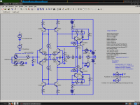
Adding a diode to the emitter of Q10 and Q11 would get the Baxandall drivers out of danger of quasi-saturation, but I don't know if this would bring any benefits to the circuit. Maybe better PSRR. Using a Widlar or other suitable current mirror to increase the Vce of the current mirrors may bring an improvement in current balance for the same reason.
I only started understanding most of this stuff in an organized way this year, and I've just graduated from HS, so be advised...
I found your capacitor trick to be entirely ineffective at curing oscillation in simulation, and it caused problems of it's own. This cascode has VERY specific needs. Specs are not as great after compensation, but this is a necessity.
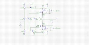
Attached is what I came up with to stabilize the Baxandall cascode. This gets it stable, and with more extreme values it can be made unconditionally stable. I don't know if it can be stable any other way. The simulator suggests it has stability as-is, but I doubt it works like that in real life. Unfortunately this causes signal loss through the bias generator, but it's not too much at audio frequencies.
The diode is included to get the Baxandall driver out of quasi-saturation. Leakage between the base and collector (Early, w/e) decreases max output impedance (we control this specifically with the 47k resistor, which helps stability), so quasi-saturation is good to avoid. I'm not sure but I think it's necessary in real life. The 47k resistor is placed so there is no DC bias across it. May not matter, but why not?
Increasing the 1k resistor decreases the effectiveness of the cascode since it sort of degenerates the driver through the base. 1k was a good compromise, as far as cascode performance, but increasing it decreases signal loss through it and that may be more important.
If no one else has stabilized the Baxandall, let it be known that I was first!!!
THD20 is .000002% at 1V output.
Attachments
Seems like an interesting design idea, I'll load this in the simulator ASAP.
Also interesting, you changed your opinion on the TMC input stage loading and the general TPC vs. TMC performance:
This compared ompared to your previous hard stances about, e.g.:
http://www.diyaudio.com/forums/soli...erview-negative-feedback-331.html#post2420886
Also interesting, you changed your opinion on the TMC input stage loading and the general TPC vs. TMC performance:
Your web site said:TPC reduces distortion of IPS, TIS and OPS as well, though it puts a higher load on the TIS output.TMC only reduces the distortion of the TIS and OPS. However it decreases the load on the TIS output. Applied to a typical power amp topology, both compensation schemes appear to work about equally well.
This compared ompared to your previous hard stances about, e.g.:
http://www.diyaudio.com/forums/soli...erview-negative-feedback-331.html#post2420886
Instability
Hi Keane,
Using solder with traces of copper helps to avoid that the tip dissolves in the solder.
To a certain extent I share your concern about quasi saturation (I wish I had better models). On the other hand, I've seen many circuits with transistors operating at Vce ~= 0.6V. But if it works, I prefer it this way, as one of objectives was a near rail to rail output swing. This is because I hate using an elevated and/or separate PSU for the front-end.
Other people have reported instabilities as well, but I haven't encountered them yet. Dimitri Danyuk has built similar circuits (see his AES paper), but no mention about instability (BTW, the Baxandall transistors in his circuit operate at 0.6V). I have also simmed the circuit with other transistor models (2N5401, 2N5551, 2SA1407 & 2SC3601) but no sign of instability. So what's going on? Has it something to do with the spice models?
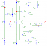
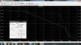
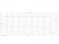
As for the capacitor trick (470pF), these caps do have an effect according the test circuit as shown below, fig.1.
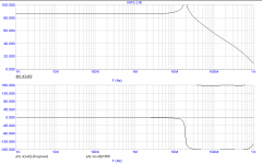
Fig. 2: C1 = C2 = C3 = 0. It peaks at 19MHz.
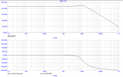
Fig. 3: C1 = C2 = 470pF, C3 = 0
Fig. 4: C1 = C2 = 0, C3 = 10pF
As you see, no sign of instability with either of these caps.
Anyhow, can you give me the models of your transistors (in spice format, no LT format, please)? Maybe it will provide a clue.
BTW, the 100k bias resistors are wrong connected (not a fatal error, I think).
Cheers,
E.
I would like to be called Keane. My wishful thinking is that my accomplishments will be known under that name...
I would be flattered to build your frontend too, unfortunately my bench is not that great (yet) and I'm of limited means. My soldering iron tip has corroded again, and who knows when I'll be able to get another one.
Hi Keane,
Using solder with traces of copper helps to avoid that the tip dissolves in the solder.
Adding a diode to the emitter of Q10 and Q11 would get the Baxandall drivers out of danger of quasi-saturation, but I don't know if this would bring any benefits to the circuit. Maybe better PSRR. Using a Widlar or other suitable current mirror to increase the Vce of the current mirrors may bring an improvement in current balance for the same reason.
To a certain extent I share your concern about quasi saturation (I wish I had better models). On the other hand, I've seen many circuits with transistors operating at Vce ~= 0.6V. But if it works, I prefer it this way, as one of objectives was a near rail to rail output swing. This is because I hate using an elevated and/or separate PSU for the front-end.
I only started understanding most of this stuff in an organized way this year, and I've just graduated from HS, so be advised...
I found your capacitor trick to be entirely ineffective at curing oscillation in simulation, and it caused problems of it's own. This cascode has VERY specific needs. Specs are not as great after compensation, but this is a necessity.
Attached is what I came up with to stabilize the Baxandall cascode. This gets it stable, and with more extreme values it can be made unconditionally stable. I don't know if it can be stable any other way. The simulator suggests it has stability as-is, but I doubt it works like that in real life. Unfortunately this causes signal loss through the bias generator, but it's not too much at audio frequencies.
The diode is included to get the Baxandall driver out of quasi-saturation. Leakage between the base and collector (Early, w/e) decreases max output impedance (we control this specifically with the 47k resistor, which helps stability), so quasi-saturation is good to avoid. I'm not sure but I think it's necessary in real life. The 47k resistor is placed so there is no DC bias across it. May not matter, but why not?
Increasing the 1k resistor decreases the effectiveness of the cascode since it sort of degenerates the driver through the base. 1k was a good compromise, as far as cascode performance, but increasing it decreases signal loss through it and that may be more important.
If no one else has stabilized the Baxandall, let it be known that I was first!!!
THD20 is .000002% at 1V output.
Other people have reported instabilities as well, but I haven't encountered them yet. Dimitri Danyuk has built similar circuits (see his AES paper), but no mention about instability (BTW, the Baxandall transistors in his circuit operate at 0.6V). I have also simmed the circuit with other transistor models (2N5401, 2N5551, 2SA1407 & 2SC3601) but no sign of instability. So what's going on? Has it something to do with the spice models?
As for the capacitor trick (470pF), these caps do have an effect according the test circuit as shown below, fig.1.
Fig. 2: C1 = C2 = C3 = 0. It peaks at 19MHz.
Fig. 3: C1 = C2 = 470pF, C3 = 0
Fig. 4: C1 = C2 = 0, C3 = 10pF
As you see, no sign of instability with either of these caps.
Anyhow, can you give me the models of your transistors (in spice format, no LT format, please)? Maybe it will provide a clue.
BTW, the 100k bias resistors are wrong connected (not a fatal error, I think).
Cheers,
E.
Attachments
Last edited:
BTW, Some comparisons with a few other front-ends:
PGP: complexity: 45 trannies, THD20k = 53ppb
Super TIS: complexity: 18 trannies, THD20k = 74ppb
Bob's HEC: complexity: 19 trannies, THD20k = 1057ppb
My complete amp http://www.diyaudio.com/forums/solid-state/182554-thermaltrak-tmc-amp-5.html#post2856556 23 transistors all together with two output pairs simulate THD20k = 100ppb at 70W on 8 ohm.
dado
100 ppb
Hi Dado,
Congratulations! For an amp of limited complexity, that is an extreme good figure.
BTW, did you check the phase margin of the internal Miller loop as well as the global NFB loop?
Cheers,
E.
My complete amp http://www.diyaudio.com/forums/solid-state/182554-thermaltrak-tmc-amp-5.html#post2856556 23 transistors all together with two output pairs simulate THD20k = 100ppb at 70W on 8 ohm.
dado
Hi Dado,
Congratulations! For an amp of limited complexity, that is an extreme good figure.
BTW, did you check the phase margin of the internal Miller loop as well as the global NFB loop?
Cheers,
E.
Hi Edmond,
Saw your thread only today. Looks interesting!
You asked about origin - I am not sure, and need to research this further, but it reminds me of an opamp simplified circuit I have seen.
Maybe I can find it, and maybe it is different. But it IS creative.
jan didden
Saw your thread only today. Looks interesting!
You asked about origin - I am not sure, and need to research this further, but it reminds me of an opamp simplified circuit I have seen.
Maybe I can find it, and maybe it is different. But it IS creative.
jan didden
Hi Dado,
Congratulations! For an amp of limited complexity, that is an extreme good figure.
BTW, did you check the phase margin of the internal Miller loop as well as the global NFB loop?
Cheers,
E.
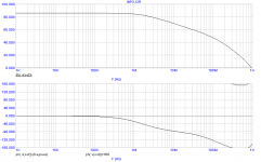
Here are two feedback loop gain plots. First one with TMC resistor connected after the probe, and second one is with TMC resistor connected to the output. I tried before to simulate the internal Miller loop but with very strange result and I think I am doing it wrongly.
cheers dado
Attachments
Hi Edmond
As others are saying, it's an interesting circuit, I tried something similar one or two years ago (not the same IPS and CM, but the TIS, and a TIS also with a bootstrapped super pair) I got the same peaking around 19MHz and was unable to fix it without a big drop in performance, so I gave up the whole idea. And forgot the circuit until I saw your circuit.
Your idea, by using C1 and C2 (in the TIS test setup) seems to fix the problem.
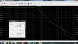
BTW: I tried something else today, try to use the attached models for Q7 and Q8 in the TIS test, these are NXP advanced models (better quasi sat. models). see attached picture (without C1 and C2).
BTW 2: I have been busy with other things the last months, but have finished the amp I emailed you some months ago, rock stable.
Cheers
Stein
As others are saying, it's an interesting circuit, I tried something similar one or two years ago (not the same IPS and CM, but the TIS, and a TIS also with a bootstrapped super pair) I got the same peaking around 19MHz and was unable to fix it without a big drop in performance, so I gave up the whole idea. And forgot the circuit until I saw your circuit.
Your idea, by using C1 and C2 (in the TIS test setup) seems to fix the problem.
BTW: I tried something else today, try to use the attached models for Q7 and Q8 in the TIS test, these are NXP advanced models (better quasi sat. models). see attached picture (without C1 and C2).
BTW 2: I have been busy with other things the last months, but have finished the amp I emailed you some months ago, rock stable.
Cheers
Stein
Attachments
Hi Edmond
As others are saying, it's an interesting circuit, I tried something similar one or two years ago (not the same IPS and CM, but the TIS, and a TIS also with a bootstrapped super pair) I got the same peaking around 19MHz and was unable to fix it without a big drop in performance, so I gave up the whole idea. And forgot the circuit until I saw your circuit. Your idea, by using C1 and C2 (in the TIS test setup) seems to fix the problem.
Hi Stein,
Indeed, seems to fix the problem. However, Keane has still troubles with it.
BTW: I tried something else today, try to use the attached models for Q7 and Q8 in the TIS test, these are NXP advanced models (better quasi sat. models).
Thanks for the models, though one question: the additional components in the PNP model seems to be missing in the NPN model. Is this correct?
see attached picture (without C1 and C2).
Is this picture from my test setup up or a different one?
BTW 2: I have been busy with other things the last months, but have finished the amp I emailed you some months ago, rock stable.
Cheers
Stein
I suppose you mean the amp with the H-bridge input stage and diamond driver, right?
Glad to hear it's working so well.
Cheers,
E.
PS: Any news from 'overthere'?
Hi Edmond
Has Kean told you what kind of troubles he has with the C solution?
It's quite easy to see the results if you run an AC analysis and stepping the C's.
Depending on the rest of the circuit you will find an optimum value for the C's
I'm using factory models for all the transistors, I guess Kean is using Bob's (better)models.
I don't know why NXP don't include the extra components in both models.
The picture in my previous post are from your test setup, see attached picture of the setup I'm using.
Yes it's the H bridge with the "Diamond" ops. ( if the contest is to use as few tranistors as possible, I'm a looser).
No, no news from over there.
Cheers
Stein
Attachments
Hi Keane,
To a certain extent I share your concern about quasi saturation (I wish I had better models). On the other hand, I've seen many circuits with transistors operating at Vce ~= 0.6V. But if it works, I prefer it this way, as one of objectives was a near rail to rail output swing. This is because I hate using an elevated and/or separate PSU for the front-end.
Other people have reported instabilities as well, but I haven't encountered them yet. Dimitri Danyuk has built similar circuits (see his AES paper), but no mention about instability (BTW, the Baxandall transistors in his circuit operate at 0.6V). I have also simmed the circuit with other transistor models (2N5401, 2N5551, 2SA1407 & 2SC3601) but no sign of instability. So what's going on? Has it something to do with the spice models?
As for the capacitor trick (470pF), these caps do have an effect according the test circuit as shown below, fig.1.
Fig. 2: C1 = C2 = C3 = 0. It peaks at 19MHz.
Fig. 3: C1 = C2 = 470pF, C3 = 0
Fig. 4: C1 = C2 = 0, C3 = 10pF
As you see, no sign of instability with either of these caps.
Anyhow, can you give me the models of your transistors (in spice format, no LT format, please)? Maybe it will provide a clue.
BTW, the 100k bias resistors are wrong connected (not a fatal error, I think).
Cheers,
E.
I use Bob Cordell's models, from here. I thought LTSpice was compatible with normal SPICE.
CordellAudio.com - SPICE Models
It is believable that there would not be stability problems at low Vce, if the BC junction had more leakage than the 47k resistors in my schematic. As I recall a normal BJT CCS can have 100k impedance just from C-B leakage, regardless of the emitter current feedback loop. The cascodes may not be operating in full capacity. SPICE may also be pessimistic. I found it was unstable, but would not oscillate, with 100k resistors which is why I increased them to 22k, so I could look at how to stabilize the circuit. Another reason to increase these resistors is to have higher slew rate.
In looking for instability you are looking in the wrong place. It will not occur as a kind of peaking in response. It is internal to the cascode current loop and occurs at much higher frequencies; to me it appears as a resonance or extreme phase shift around 100MHZ. It is easiest to observe if you hang a 1F cap to ground from the feedback point so the TIS operates open-loop at high frequencies. It is a kind of parasitic instability, but it grows until it throws the cascode into repeated saturation. If uncompensated, you may get away with it but the peaking will probably still be there, and the circuit may have anomalous problems.
Now I must read the new replies...
By "undonditionally stable" I mean it will be stable with any impedance load. Many circuits are stable without peaking normally but will oscillate into certain reactive loads.
The Baxandall cascodes seem to like to oscillate with 10u inductors at their output. A feedback loop can emulate inductances, and for this reason the cascode may not behave like a normal common-emitter circuit.
The Baxandall cascodes seem to like to oscillate with 10u inductors at their output. A feedback loop can emulate inductances, and for this reason the cascode may not behave like a normal common-emitter circuit.
Last edited:
I
[snip]
If no one else has stabilized the Baxandall, let it be known that I was first!!!
THD20 is .000002% at 1V output. [E: i.e. 0.02ppm]
Hi Keane,
With your circuit I get 0.06ppm, BUT if Vcc=50V and Vo=40V then THD20k=5.8ppm.

So, this doesn't work, sorry.
Cheers,
E.
Internal affair
So it's an 'internal affair'. Therefore I've put a Tian gain probe at one of the Baxandall loops (circuit of post 44). Without any caps the phase/gain response is indeed problematic, on the verge of instability, but again at 19MHz, not 100MHz.
With a tiny cap at the output (10pF or so) the loop is stable (a gain margin of about 12dB).
Cheers,
E.
Hi Keane,[...]
In looking for instability you are looking in the wrong place. It will not occur as a kind of peaking in response. It is internal to the cascode current loop and occurs at much higher frequencies; to me it appears as a resonance or extreme phase shift around 100MHZ.
[...]
So it's an 'internal affair'. Therefore I've put a Tian gain probe at one of the Baxandall loops (circuit of post 44). Without any caps the phase/gain response is indeed problematic, on the verge of instability, but again at 19MHz, not 100MHz.
With a tiny cap at the output (10pF or so) the loop is stable (a gain margin of about 12dB).
Cheers,
E.
- Status
- This old topic is closed. If you want to reopen this topic, contact a moderator using the "Report Post" button.
- Home
- Amplifiers
- Solid State
- Has anyone seen this front-end before?