What pain do you want help with? The pain of wanting reality to be other than it is, or the pain of listening to a sub-standard pre? For the former, therapy is a fairly well-worn path.
The latter pain is probably going to be helped by rigorously adopting star earthing rather than relying on ground fill.
The latter pain is probably going to be helped by rigorously adopting star earthing rather than relying on ground fill.
I'm assuming you have seen this,
http://www.diyaudio.com/forums/solid-state/209004-new-doug-self-pre-amp-design-10.html#post2958582
It might be worth tagging a normal pot to before the active gain stage and having a listen to the feed from that. I found the tone control stages very transparent but I did not use the active the gain stage.
http://www.diyaudio.com/forums/solid-state/209004-new-doug-self-pre-amp-design-3.html#post2952367
Have you soldered your opamps or are they socketed ?
Yes did see those thanks - good points.
I was thinking Bob Cordell's concern over low Z would not be as much concern in this design as it uses 10k pots, but perhaps it holds for this design too without the paralleled opamps.
Interesting you didn't use the Baxandall gain control - perhaps that's what I'm hearing...
I used high quality sockets as it's a DSPT board and I thought I might try different 5532 brands out of curiosity and maybe others like the '4562. Do you think they're bad news?
Yes did see those thanks - good points.
I was thinking Bob Cordell's concern over low Z would not be as much concern in this design as it uses 10k pots, but perhaps it holds for this design too without the paralleled opamps.
Interesting you didn't use the Baxandall gain control - perhaps that's what I'm hearing...
I used high quality sockets as it's a DSPT board and I thought I might try different 5532 brands out of curiosity and maybe others like the '4562. Do you think they're bad news?
Hi owdeo,
I am not familiar with this earlier version of the pre, but even without the paralled op amps it might be a relatively low-impedance design. If so, you may be hearing the 5532s struggling to drive a relatively low-impedance load and being called upon to deliver substantial current to the load. Such a situation drives the quasi-complementary 5532 output stage deeply into class B operation. Also, such operation may cause significant output stage power dissipation and consequent junction temperature variations with signal. In some cases this may lead to some form of memory distortion. There will also be some overall die temperature variations in such a situation. I admit, this is speculation on my part, especially given that I don't know the impedances involved.
The 5532/4 does seem to have a reputation of measuring better than it sounds. I do not use them in the signal path.
The Baxandall volumen control is an incredibly clever circuit that does a lot for you and solves or mitigates some classical volume control problems. Who knows, however, there may be some things about it that we do not fully understand that influence how it sounds.
Finally, be mindful that your prior preamp may be affecting the sound in a non-perfectly-neutral way that you have gotten used to or just happen to like.
Cheers,
Bob
I used high quality sockets as it's a DSPT board and I thought I might try different 5532 brands out of curiosity and maybe others like the '4562. Do you think they're bad news?
Have to admit I haven't used the 4562 in any of my work to date.
The 5534/2 can definitely sound poor in certain situations... I hate saying that because it is purely a subjective opinion and one where I have never found an obvious reason why... and yet in other situations it can sound very transparent indeed with the precision preamp being one such design (but without the active gain stage remember).
Ultimately you have to listen for yourself and keep an open mind. The OPA2134 is an excellent all rounder for many audio applications I have found.
I like the OPA2134 as well. I have a general preference to JFET op amps anyway. However, there are tradeoffs between them and BJT-input op amps. Choose your poison carefully and with the right priorities.
Cheers,
Bob
I am not familiar with this earlier version of the pre, but even without the paralled op amps it might be a relatively low-impedance design. If so, you may be hearing the 5532s struggling to drive a relatively low-impedance load and being called upon to deliver substantial current to the load. Such a situation drives the quasi-complementary 5532 output stage deeply into class B operation. Also, such operation may cause significant output stage power dissipation and consequent junction temperature variations with signal. In some cases this may lead to some form of memory distortion. There will also be some overall die temperature variations in such a situation. I admit, this is speculation on my part, especially given that I don't know the impedances involved.
Thanks for your helpfull advice Bob. The '96 design uses the same output stage configuration as the 2012 preamp but without the paralleled opamps - there is just one set (eg IC5A and IC5B) and the pot value is 10k instead of 1k. The maximum-gain-setting resistors are 680R (R21) and 4k7 (R53) as the gain structure is designed for lower-level inputs than the current design.
I would have thought this should be less of a concern given the pot is 10 times the value even though the opamp drive capability is 1/4 in relation to the current design. If I understand your previous post correctly this potential problem should be at its worst when the gain is set near minimum? As the CD input has a 16dB resistive attenuator I can check this easily by plugging the CD player into one of the other line level inputs and comparing the result. With the CD input the gain will be set quite high but with any other input it will need to be quite low. I will have to try and measure the pot positions that give exactly the same output level though.... I'll try this and report back.
Finally, be mindful that your prior preamp may be affecting the sound in a non-perfectly-neutral way that you have gotten used to or just happen to like.
True and I did consider this, but as I have several other preamps of very different design and the aspect of SQ I'm unhappy about applies when compared to any of them, I don't think this is the case. I attend plenty of acoustic concerts and also play an instrument so I think I at least try to give my subjective judgements a reference to the real thing as much as possible!
To exaggerate it's as though the music is being strangled and is somehow constrained, the sense of music flowing freely is somehow reduced.
Gentlemen, unfortunately I have to disagree with both of you re the OPA2134 SQ. I agree Mooly that making unqualified subjective assessments is of limited value, but taste has to come into it at some point 
I've tried it both in a DAC output stage and in a conventional preamp with a volume pot and fixed gain and found it to be very flat and boring. The top end was very clean and pleasant, but the bass was anaemic and the midrange not tonally correct to my ears - brass instruments particularly just didn't sound natural. I really disliked it.
I also tried the OPA2604 in both those circuits and found it to be much more to my liking, so I'd stick with that if I had to use jfet opamp. But overall I normally really like the 5532, hence my diving into building a preamp littered with them! No doubt with any opamp it really depends on how and where they are used, but as the Self preamp was specifically designed around the 5532 I guess I was expecting more.
Owedo, what pre-amp were you using before you built this one?
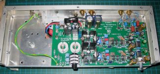
The current favourite of both myself and SWMBO in fact also uses the Baxandall gain control but with discrete opamp output stage after it and was published in Silicon Chip magazine as a headphone amp. See attached as build into an old ugly but serviceable case.
It consists of an opamp input buffer, then the Baxandall gain control (almost exactly per Self) but this then drives a discrete opamp in inverting configuration (gain -1) to restore the phase and minimise input common-mode distortion. The output stage uses TIP31/32s idleing at 47mA and I took the line outputs via 47R resisitors before the output Zobel networks. This is way overkill for a line preamp but I can't help but think this is why it sounds so great - maybe driving a power amp input is more taxing of the preamp that we are all considering? I also can't see how this extra output stage gets around the potential opamp driving problem in the active gain stage, and yet it sounds so much better....
I also have a conventional two-opamp pre with an input buffer, 10k log pot and an output stage with gain of about 5.
There's also a fully discrete preamp with just a pot at the front. The input and VAS stages are both differential. It was published in AEM back in '86 as a companion to the 6000 Ultra-Fidelity mosfet power amp, still an amazing power amp.
Attachments
Hold on guys - I've just replaced the 6 Fairchild 5532s in the main signal path with On Semi NE5532ANs. MUCH better, I just cannot believe how different it sounds. The mid and treble is completely cleaned up and instruments have air around them and sound tonally correct. And luckily the bass still kicks you-know-what too.
The sound is still slightly "tight" or "overdamped" or something, but on many recordings this works just fine. Most of what was bugging me about the sound has now gone.
I know this is crazy but it seems 5532s are not 5532s and the brand is very important. I originally bought Farichilds as Elektor published some test results showing that these had the lowest THD overall. But I since came across this site:
5532 IC - BRAND's, Suffix/Prefix, Differences
and while skeptical wanted to try this out for myself out of curiosity. I've also ordered some JRC ones to try and will report back on those if I bother to change them since the On Semi's sound so good now. I might also try some old Signetics ones I have, but I only have 4 of 'em.
I am completely puzzled by this. I know it's purely subjective and unscientific, but the difference is so big I'm sure it must be measureable if you could measure the right thing with the right equipment. And it's clearly not just down to the THD curve if the Fairchild's are the best in this regard.
try DiffMaker Audio DiffMaker and a decent soundcard - even use 24/192 if you want
you could use foobar ABX plugin to do blind listening
you could multiply the DiffMker diff by 10-100x, add it to a track, compare (maybe with added random noise to the other track to match the noise floors)
I'm betting against "clearly audible" results when you try some controls, level matching, blinding
Seems diffmaker's algorithm for finding the optimum null is flawed - see the posts of panatrope on this (very long) Gearslutz saga: Gearslutz.com - View Single Post - The Ultimate Converter DA/AD Loopback Shootout Thread!
10-pin header and 2-channel operation?
Hi Guys,
Changing topics just a little bit.... I'm in the process of building the new Pre-2012. I've just about got all the boards completed - but not yet tested. I was doing some final soldering tonight on the 2 inputs boards and noticed they both have a 10-pin header for connecting to the front-panel switch PCB. I was also re-reading through the final construction article and noticed that the front-panel (FP) switch PCB only has 1, 10-pin header! So, where does the other input board connect? It was never called out in the article that you needed 2 FP-switch PCBs. Perhaps in my haste when I ordered all the PCBs I neglected 2 of those PCBs. Now I'm left wondering how all of this 'fits' together. Elektor never mentioned you would need 2 of the FP switch PCBs - but it looks like you do. Do you need 2 FP switch PCB for stereo operation, or do you just connect the FP switch PCB to one channel? How does a single FP-switch PCB control both channels? If indeed you do use 2 FP switch boards in this project... it begs the question of how to keep the rotary switches in sync instantaneously, and if you don't could bad things happen?
This is my first 'big' pre-amp project, and like most projects I move slowly to avoid unnecessary problems. I want to make sure I've got everything covered, but this discovery tonight has me perplexed. Am I missing or over-looking something very simple or obvious here. I'm sure there's a perfectly reasonable answer, but do I need to buy another FP-switch PCB? Back to the article for more clues.
redjr
Hi Guys,
Changing topics just a little bit.... I'm in the process of building the new Pre-2012. I've just about got all the boards completed - but not yet tested. I was doing some final soldering tonight on the 2 inputs boards and noticed they both have a 10-pin header for connecting to the front-panel switch PCB. I was also re-reading through the final construction article and noticed that the front-panel (FP) switch PCB only has 1, 10-pin header! So, where does the other input board connect? It was never called out in the article that you needed 2 FP-switch PCBs. Perhaps in my haste when I ordered all the PCBs I neglected 2 of those PCBs. Now I'm left wondering how all of this 'fits' together. Elektor never mentioned you would need 2 of the FP switch PCBs - but it looks like you do. Do you need 2 FP switch PCB for stereo operation, or do you just connect the FP switch PCB to one channel? How does a single FP-switch PCB control both channels? If indeed you do use 2 FP switch boards in this project... it begs the question of how to keep the rotary switches in sync instantaneously, and if you don't could bad things happen?
This is my first 'big' pre-amp project, and like most projects I move slowly to avoid unnecessary problems. I want to make sure I've got everything covered, but this discovery tonight has me perplexed.
Am I missing or over-looking something very simple or obvious here. I'm sure there's a perfectly reasonable answer, but do I need to buy another FP-switch PCB? Back to the article for more clues. redjr
certainly disapointing info if the DiffMaker doesn't at least match minimum phase filter's phase shift differences correctly
but how much will this cut from the null with op amp rolling in a active filter with the exact same passive/feedback corner frequency, low Q - the ideal filter response isn't changing between measurements - only the 2nd order effects from swapped op amp gain, output Z differences - with typical op amp GBW to filter corner easily >100x and the constant delay, linear phase term correctly compensated?
but how much will this cut from the null with op amp rolling in a active filter with the exact same passive/feedback corner frequency, low Q - the ideal filter response isn't changing between measurements - only the 2nd order effects from swapped op amp gain, output Z differences - with typical op amp GBW to filter corner easily >100x and the constant delay, linear phase term correctly compensated?
Hold on guys - I've just replaced the 6 Fairchild 5532s in the main signal path with On Semi NE5532ANs. MUCH better, I just cannot believe how different it sounds.
Have you considered using different opamps in different parts of the circuit to achieve the sound you want ?
Second time in a couple of days I have mentioned the TLE2072 Excaliber opamp which has a -/+80 ma drive ability. Has anyone tried these ?
Sorry guys I don't have a good soundcard (yet), hobby budget blown on a preamp I don't like the sound of
On further listening, while the On Semi 5532s have much improved the tonality, detail and soundstage, the slightly compressed or restricted character remains. I've swapped preamps back and forth several times now and each time I go back to one of the others it just seems as though the music flows more easily and dynamic contrasts are greater.
I really think it must be related to the way feedback is used in this AGC configuration, but perhaps the output opamp struggling to drive the pot Z at high attenutation at the same time as the power amp input. This could explain why my other pre with this AGC config but driving the power amp via a beefy discrete opamp buffer sounds so much more dynamic.
You might be right Mooly - maybe what's needed is a beefier opamp. I don't have any TLEs but I could try the LM4562 since I have some (after checking it's stable first of course), it has a similar current capability from memory and we know the THD is equivalent to or better than the 5532.
What I find mysterious about all this is how much difference the preamp seems to make to the final sound of the system. In theory it should be the least critical part, but I think it makes far more difference than the power amp
On further listening, while the On Semi 5532s have much improved the tonality, detail and soundstage, the slightly compressed or restricted character remains. I've swapped preamps back and forth several times now and each time I go back to one of the others it just seems as though the music flows more easily and dynamic contrasts are greater.
I really think it must be related to the way feedback is used in this AGC configuration, but perhaps the output opamp struggling to drive the pot Z at high attenutation at the same time as the power amp input. This could explain why my other pre with this AGC config but driving the power amp via a beefy discrete opamp buffer sounds so much more dynamic.
You might be right Mooly - maybe what's needed is a beefier opamp. I don't have any TLEs but I could try the LM4562 since I have some (after checking it's stable first of course
), it has a similar current capability from memory and we know the THD is equivalent to or better than the 5532.What I find mysterious about all this is how much difference the preamp seems to make to the final sound of the system. In theory it should be the least critical part, but I think it makes far more difference than the power amp
Changing topics just a little bit.... I'm in the process of building the new Pre-2012. I've just about got all the boards completed - but not yet tested. I was doing some final soldering tonight on the 2 inputs boards and noticed they both have a 10-pin header for connecting to the front-panel switch PCB. I was also re-reading through the final construction article and noticed that the front-panel (FP) switch PCB only has 1, 10-pin header! So, where does the other input board connect? It was never called out in the article that you needed 2 FP-switch PCBs. Perhaps in my haste when I ordered all the PCBs I neglected 2 of those PCBs. Now I'm left wondering how all of this 'fits' together. Elektor never mentioned you would need 2 of the FP switch PCBs - but it looks like you do. Do you need 2 FP switch PCB for stereo operation, or do you just connect the FP switch PCB to one channel? How does a single FP-switch PCB control both channels? If indeed you do use 2 FP switch boards in this project... it begs the question of how to keep the rotary switches in sync instantaneously, and if you don't could bad things happen?
Hi redjr,
From a quick skim of the article, although they haven't mentioned anything it looks as though you just need to parallel them - ie crimp two 10 pin IDC sockets, one for each input board, on one end of the ribbon cable and one 10 pin IDC socket on the other end for the front panel board.
As each input of each channel is switched with a seperate relay it makes sense that the two input boards need to be connected in parallel to a common switch so that the same input is always selected on both channels at the same time.
One curious thing is that they have put 220n caps across the relay coils. Normally the spike produced by the relay coil inductance at switch off is damped using a reverse connected diode. But since the relay coils are switched directly using switch contacts this shouldn't be a problem anyway. Maybe they are to delay the switching time slightly to give a "make before break" sort of input switching action?
WRT to the 5532/34's I would imagine that in the detail there are quite some differences. Not all the vendors publish internal circuits IIRC, so who knows what the designers have added/omitted in the circuit. Typically, an IC designer will get a spec, there will be a lot of research, modelling etc and loads of pressure to reduce die area and get yields up from the marketers (who in the vast majority of cases are ex designers . . . ).
Then theres the differences in process between the various vendors. Since the 5532/34 are bipolar devices, most of these will be done in house - not like for example having a TSMC C14 jellybean process that is 95% the same between all their customers.
So, that 5532/34's are different should not surprise us . . . best to follow the advice of DS and the previous posters and stick with what we know sounds best.
The other option for you to try BTW owedo is the LM4562. Sound preference is a personal thing, buy I got a very good result on my X-Altra mini pre-amp - measured and sonics.
I thot of paralleling too. The only place in the article they mention the 10-pin ribbon cable refers to a connector on both ends. No talk of 2 connectors on one end, but it does make sense. I suspect that part will have to be homemade, as it might be very hard to source something like that. I managed to get an 11" piece with one connector on each end from eBay. Now all I need to do is crimp another connector on one end.Hi redjr,
From a quick skim of the article, although they haven't mentioned anything it looks as though you just need to parallel them - ie crimp two 10 pin IDC sockets, one for each input board, on one end of the ribbon cable and one 10 pin IDC socket on the other end for the front panel board.
As each input of each channel is switched with a seperate relay it makes sense that the two input boards need to be connected in parallel to a common switch so that the same input is always selected on both channels at the same time.
One curious thing is that they have put 220n caps across the relay coils. Normally the spike produced by the relay coil inductance at switch off is damped using a reverse connected diode. But since the relay coils are switched directly using switch contacts this shouldn't be a problem anyway. Maybe they are to delay the switching time slightly to give a "make before break" sort of input switching action?
- Home
- Source & Line
- Analog Line Level
- New Doug Self pre-amp design...