Hello everyone!
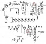
I want to make the party phono MM and I drew a circuit accordingly. I just have a little problem on the size that some capacitors (circled in red in the image).
My question: These two capacitors are 35V voltage isolation but with isolation voltage of 25V is suitable?
Thank you!
I want to make the party phono MM and I drew a circuit accordingly. I just have a little problem on the size that some capacitors (circled in red in the image).
My question: These two capacitors are 35V voltage isolation but with isolation voltage of 25V is suitable?
Thank you!
Attachments
These two capacitors are 35V voltage isolation but with isolation voltage of 25V is suitable?
Yes, The power supply is only +/-17 V, so 25V capacitors are fine.
You might consider non-polarized electrolytics. They are thought to sound better,
and the polarity of voltage on those caps in your circuit can vary.
Also, have you considered using a ground plane?
Last edited:
Thank you for the answer on the capacitors

I have asked on a French forum and the answer was that a ground plane is not necessary.Also, have you considered using a ground plane?
for an audio coupling capacitor, it is important that it is able to tolerate both -ve and -ve bias during variations of the signal.
It is reported that distortion due to the electrolytic is reduced by using back to back electrolytics.
This applied to both back to back polarised electrolytics and to back to back bi-polar electrolytics.
In order of reducing distortion:
polar electro, bi-polar electro, back to back polar electro, back to back bi-polar electro, MKT film type, MKP film type.
The back to back bi-polar perform almost as good as MKT when used as a filter.
In audio coupling duty, the caps do not operate as a filter of the audio frequencies. The distortion reduces massively for this duty. I suspect that had the measurements been done where the RC was only filtering the sub-audio frequencies, that the author may not have been able to measure any audio distortions. His equipment had to be developed (extensively) just to present the higher "filtered" style distortions.
Hello everyone!
I want to make the party phono MM and I drew a circuit accordingly. I just have a little problem on the size that some capacitors (circled in red in the image).
My question: These two capacitors are 35V voltage isolation but with isolation voltage of 25V is suitable?
Thank you!
Consider using radial Nichicon NP electrolytics designed for loudspeaker crossovers. A good example is 10uF at 100V. Higher-voltage NP electrolytics tend to introduce less distortion. I discuss this in my book and show measurements.
Cheers,
Bob
5000 preamp and the sound of ne5534an op-amps
Hi Ian,
You are right that the sound of the 5000 preamp was not limited by the performance of the 5534 op-amps. I made a mistake in that design, which to some extent, is relatively easy to fix.
As you know, the 5000 preamp was designed in an era when we almost exclusively used vinyl as our primary source, and it was very common practice to make tape copies, with to reel/reel or cassette tape formats for "everyday" listening. So the 5000 was not aimed at professional applications, per se, nor was it a minimalist audiophile preamp.
The topology had a number of design objectives to try to ensure good quality tape copies from vinyl or reel-reel sources: low distortion, a low noise phono stage, very versatile tape-tape dubbing capability and effectively total immunity to overload and clipping regardless of he type of phono cartridge used. Hence the dual level controls at different gain points, the high speed peak detecting LED meters and the internal reference tone for setting recording reference levels.
In order to ensure maximum flexibility for tape dubbing etc it was possible to select any input as a recording source. The downside of this flexibility, however, was that when the tape recorders were operated in monitor mode it was possible to select a tape recorder as its own input, with the possibility of large positive positive feedback signals. To prevent this problem the design incorporated a muting system which would mute the output in the event that the same source was selected as both input and output.
I believe that this muting circuit is responsible for a degradation in the sound quality of the preamp. Had I used reed relays for example, it may not have been a problem, but as you know I elected to use bipolar junction transistors in an unconventional switched mode to achieve low saturation resistance and hence good muting when muting was needed, but very high off-restance when not in use. To achieve this I used the transistors "backwards"' using the collector-base junction to control the base-emitter junction. This works very well, and is significantly better than using the transistor conventionally. Unfortunately, it does not work quite well enough, and although it had no significant effect on measured THD performance, I realised some years after publication that the muting circuit was causing some degradation in overall sound quality.
So, if you still have a 5000 lying around from 35 years ago, I suggest you try removing all of these muting transistors. I am aware of a few 5000 owners who have done this and have reported better subjective results. It would be an interesting experiment and I would be interested to hear what you think.
When I used the 5534AN I was not aware of any other designs using the device worldwide, and was introduced to it by the Philips engineers. It is still a capable audio op-amp, even by today's standards, although there are significantly better op amps around now, of course. As it was explained to me at the time by Philips engineers, the excellent noise figures for the "AN" specification were obtained through the use of a separate dye for the input differential pair, which were effectively BC109c transistors. These were handwired to the rest of the IC.
More generally, however, I am cautious about using even the best op amps available in a new design. I much prefer to design using discrete devices so that the properties of individual stages and the open-loop and closed-loop transfer functions of the design can be properly controlled.
All the best
Dave
That one dates from around 1981 and I still have mine, replete with Signetics 5534ANs. Sadly, friends I was trying to impress with my build, dis'd it outright, whatever mods I made and I did try every sensible recommendation I could find. This was nothing to do with op-amp quality but the overall design, power supplies and layout, as I later found in an abbreviated version, using the same active circuit designs.
With its forest of shielded wiring, flashy 20-LED meters, calibration tone and many controls, it was aimed at wanna-be pro audio guys rather than audiophiles, IMO.
Hi Ian,
You are right that the sound of the 5000 preamp was not limited by the performance of the 5534 op-amps. I made a mistake in that design, which to some extent, is relatively easy to fix.
As you know, the 5000 preamp was designed in an era when we almost exclusively used vinyl as our primary source, and it was very common practice to make tape copies, with to reel/reel or cassette tape formats for "everyday" listening. So the 5000 was not aimed at professional applications, per se, nor was it a minimalist audiophile preamp.
The topology had a number of design objectives to try to ensure good quality tape copies from vinyl or reel-reel sources: low distortion, a low noise phono stage, very versatile tape-tape dubbing capability and effectively total immunity to overload and clipping regardless of he type of phono cartridge used. Hence the dual level controls at different gain points, the high speed peak detecting LED meters and the internal reference tone for setting recording reference levels.
In order to ensure maximum flexibility for tape dubbing etc it was possible to select any input as a recording source. The downside of this flexibility, however, was that when the tape recorders were operated in monitor mode it was possible to select a tape recorder as its own input, with the possibility of large positive positive feedback signals. To prevent this problem the design incorporated a muting system which would mute the output in the event that the same source was selected as both input and output.
I believe that this muting circuit is responsible for a degradation in the sound quality of the preamp. Had I used reed relays for example, it may not have been a problem, but as you know I elected to use bipolar junction transistors in an unconventional switched mode to achieve low saturation resistance and hence good muting when muting was needed, but very high off-restance when not in use. To achieve this I used the transistors "backwards"' using the collector-base junction to control the base-emitter junction. This works very well, and is significantly better than using the transistor conventionally. Unfortunately, it does not work quite well enough, and although it had no significant effect on measured THD performance, I realised some years after publication that the muting circuit was causing some degradation in overall sound quality.
So, if you still have a 5000 lying around from 35 years ago, I suggest you try removing all of these muting transistors. I am aware of a few 5000 owners who have done this and have reported better subjective results. It would be an interesting experiment and I would be interested to hear what you think.
When I used the 5534AN I was not aware of any other designs using the device worldwide, and was introduced to it by the Philips engineers. It is still a capable audio op-amp, even by today's standards, although there are significantly better op amps around now, of course. As it was explained to me at the time by Philips engineers, the excellent noise figures for the "AN" specification were obtained through the use of a separate dye for the input differential pair, which were effectively BC109c transistors. These were handwired to the rest of the IC.
More generally, however, I am cautious about using even the best op amps available in a new design. I much prefer to design using discrete devices so that the properties of individual stages and the open-loop and closed-loop transfer functions of the design can be properly controlled.
All the best
Dave
Last edited:
Hi David
I was surprised to see your earlier post (10.20 am here?) deleted this morning.
Thanks indeed for the detailed explanation. It seems to fit with my discovery of the occasionally disappointing sound which I have to admit, I didn't identify at first. Gosh, more than 30 years have passed since the ETI 5000 kits arrived at my door.
This was intended to be a workhorse amp/preamp for me but it needed better rotary switches, better quality caps and it saw a lot of travel around Sydney when I demo'd my own equipment. You get a wider range of feedback that way than from a circle of friends and family, on which many DIYs like myself have to rely.
I later bought more PCBs and built my own preamp version without VU meters, in a smaller case. A 1.2V CD input was fitted in place of one tape loop and a pair of signal relays were fitted at the output, omitting the transistor muting. As it was also powered from the main amplifier, it could be easily A/B compared and I believe most people who listened, thought it sounded better.
By then, I had come to appreciate the difference in somewhat clearer treble and better stereo image at moderate to higher output levels. Anyway, it was enough to receive a few offers and I gave it up for a tidy sum a few years later. The original 5000 combo is still with me for posterity.
For anyone mystified by what this is about, at post #4 here are some nice pics, including internals at AK forum.
for an audio coupling capacitor, it is important that it is able to tolerate both -ve and -ve bias during variations of the signal.
It is reported that distortion due to the electrolytic is reduced by using back to back electrolytics.
This applied to both back to back polarised electrolytics and to back to back bi-polar electrolytics.
In order of reducing distortion:
polar electro, bi-polar electro, back to back polar electro, back to back bi-polar electro, MKT film type, MKP film type.
The back to back bi-polar perform almost as good as MKT when used as a filter.
In audio coupling duty, the caps do not operate as a filter of the audio frequencies. The distortion reduces massively for this duty. I suspect that had the measurements been done where the RC was only filtering the sub-audio frequencies, that the author may not have been able to measure any audio distortions. His equipment had to be developed (extensively) just to present the higher "filtered" style distortions.
I have also shown by measurement that a higher voltage rating on NP electrolyics decreases their distortion contribution. Nichicon NP electrolytics designed for loudspeaker crossovers perform quite well.
Cheers,
Bob
I also have ETI 5000 preamp and the main reason for keeping it are my tape decks and taping to these.
I did some mods to it such as relay controlled output, alps pots, changed resistor values to get rid of gain up gain down approach, added best caps I could get, added separate power supplies for audio and for the display. Also replaced ne5534an opamps with LM series single opamps and removed MC preamp from the case so MM is directly connected to the input.
For me the worst thing about this preamp was cabling. Removing muting on inputs unfortunately comes at a price as Dave explained. I removed them and then reinstalled. Maybe one day when I have more time I'll get rid of the rest of the main board and switches and replace them with better ones and redesign the main board to accept relays on inputs and tape outputs.
Coming back to modern times does any one know if The Signal Transfer Company is still selling Douglas Self's precision preamp boards etc? I wrote to them a few months ago enquiring about RIAA boards but got no reply.
cheers,
What do you expect from an arrogant a$$hole?I wrote to them a few months ago enquiring about RIAA boards but got no reply.
That seems a bit harsh rsavas - unless of course you know him personally.What do you expect from an arrogant a$$hole?
I know for a fact that the Signal transfer company are in business as I received a preamp from them (via a friend) today. They have modified the design to deal with on/off clicks. Comparing the preamp with a Pass X2 I find the Self design to provide clearer sound with more attack. The output is rather high for my nCore 400 amplifiers, so the volume control is kept quite low. The amp is very quiet, apart from a turn-on click though the speakers (after 3 seconds). My biggest gripe is about the tone controls. They function very well and (IMHO) are definitely worth having, but the controls are small and closely packed together.. a bit too much for my fingers. I doubt whether the case or the printed legends will be very robust as I can already see marks on edges (whereas the Pass is unmarked after more than 15 years use). Anyway, from the listening point of view I can recommend the product. However, I am into building the preamp described in http://www.diyaudio.com/forums/chip-amps/199130-usable-tone-control.html which should allow me to get teh line-preamp that I need in a case of the right quality.I also have ETI 5000 preamp and the main reason for keeping it are my tape decks and taping to these.
I did some mods to it such as relay controlled output, alps pots, changed resistor values to get rid of gain up gain down approach, added best caps I could get, added separate power supplies for audio and for the display. Also replaced ne5534an opamps with LM series single opamps and removed MC preamp from the case so MM is directly connected to the input.
For me the worst thing about this preamp was cabling. Removing muting on inputs unfortunately comes at a price as Dave explained. I removed them and then reinstalled. Maybe one day when I have more time I'll get rid of the rest of the main board and switches and replace them with better ones and redesign the main board to accept relays on inputs and tape outputs.
Coming back to modern times does any one know if The Signal Transfer Company is still selling Douglas Self's precision preamp boards etc? I wrote to them a few months ago enquiring about RIAA boards but got no reply.
cheers,
... My biggest gripe is about the tone controls. They function very well and (IMHO) are definitely worth having, but the controls are small and closely packed together..
George,
How much space between controls do you need for comfortable operation?
George,
How much space between controls do you need for comfortable operation?
Hi Carl,
the problem ( and it is not just my fingers, my friends have the same problem) is that the controls are physically small and close together. I have never had this problem before with any other equipment. In the case of the Self Precision preamp the pots are mounted on a separate board which is attached by many wires to the main board. It looks like a solution to a layout/mounting problem but it is not pretty. It would probably be cleaner to mount the pots on the metalwork directly and connect to the main pcb via headers as my Pass X2 has done.
Anyway, specifically, all the tone-control knobs on the Self Precision pre-amp are tapered. The smallest are just 1 cm across and the largest are 1.5cms at the narrow ends. The gap between the tone boost/cut and its corresponding turnover frequency knob is about 1.5 cms. The two large tone control knobs are next to each other, they are 1.5 cms across and have a gap of just 1 cm between them. This forces you to use only finger tips for adjustment and a 1cm gap is just too small for normal operation.
Rather than give a specification of size/gaps I suggest just taking examples from well-known pieces of kit (the APT / Holman preamp had plenty of small controls without these problems).
I hope the above contributes to a little problem-avoidance.
George
George,
I just checked the control spacing on the prototype PCB that I sent to fab. The 'center to center' spacing is 3.175 cm (ie: 1.25 inches). The volume control is pushed further, having 4.45 cm (ie: 1.75 inch) distance. I hope this works for you!
Carl,
It works, and if it did not, I think I would get my fingers "adjusted". Seriously, I did do some outline measurements on the boards and it looked fine.
I would prefer to mount the pots directly on the board, but as ever the subject of a professional (i.e. domestically acceptable) case arises and that might force me to locate the pots off the board. A bit nearer the time I shall be casting about looking for a really good quality case that will support the controls that I need. In the meantime I am hoping to come across a few recommendations from other DIYers.
George
Yes. My details can be found here.Did Anyone built the pre amplifier made by Self?
How does it perform?
As usual Bonsai makes absolute sense. I have all of Doug Self's books and value them as essential reference material. Try challenging the cynical subjectivists to a double blind test on OA selection and they will always run a mile. Some DIYers would also rather make their own discrete component opamp rather than plug in a simple chip. Usually a total waste of time and board space. The best discrete component OA ever made was the Jensen JE990 which used an LM394 as the input diff amp. TI refuses to make this useful part now because the die was too big ! Bucks rule as u.
- Home
- Source & Line
- Analog Line Level
- New Doug Self pre-amp design...