Most amplifiers use a power supply
with a center tapped transformer on
the secondary windings. For example,
let say the transformer is rated for
1KVA, about 100v output with 10 amperes
roughly.
If I use the center tap, I can get
(50v @ 10A = 500VA) * 2 = 1KVA
Hypothetical;
What if I don't use both halves of the
secondary, what if I use only the
50V @ 10A section and don't use
the other half. Can this section
output 50V @ 20A because the other
side is not used ?
If you design a dual rail power supply
with a 1KVA transformer, can I get
1KVA out of each rail when only
one side is used at a time ?
thylantyr said:What if I don't use both halves of the
secondary, what if I use only the
50V @ 10A section and don't use
the other half. Can this section
output 50V @ 20A because the other
side is not used ?
No. The amerage output is limited by the wire gauge. In essence, you have a 500va transformer.
However, if the CT isn't soldered internally (so there are four wires on the 2ndary), you can parallel the two windings (make absolutely sure that they are phase matched).
I would bet you could get close to 900 VA but with a little looser regulation than 2x50 setup. Temp rise is the real limit. Surface area on the transfo will be the same, resistive heating will be doubled in the one winding if current is doubled, but there will be no heating in the unused coil, so you'll have the same total temp rise by only loading one coil. But that coil may not be able to dissapate as well and could risk cooking varnish, so don't expect UL approval.
This is not the best way to set up a good psu, but you will have much more current reserves than a 50V 500VA transformer, but don't expect 1200 VA continuous.
Brian/ putting on flameproof suit and awaiting attacks from all sides.
This is not the best way to set up a good psu, but you will have much more current reserves than a 50V 500VA transformer, but don't expect 1200 VA continuous.
Brian/ putting on flameproof suit and awaiting attacks from all sides.
This is just a theoretical question,
wire gauge is not factored in.
Hypothetical;
Assume 100% efficient amplifier.
If your ideal amplifier is 1000 watts
and you need to design a power
supply, do you need just a 1KVA transformer (500VA per rail)
or do you need a 2KVA
transformer (1KVA per rail)
to supply power to your 1000w amp?
Only one rail operates at any given
moment in time.
I realize this is not the ideal way
to design a power supply as most
good engineers factor in safety margins,
but I just want to know if it works
this way.
A normal amplifier is ~70% efficent, to put out 70W it will need 100W in.
A normal amplifier power supply will have the rectifiers feeding large filter caps, a brute force pseudo regulated supply if you will.
The power factor on this will be ~.7, so you will need a 100VA trafo to output 70W.
So we need a 140VA trafo for a 70W amplifier.
Highly compressed rock/rap music has a 50% duty cycle, but a real speaker may look like a 45* load. Call it a wash.
Rule-of-thumb = 2VA for 1W out.
I have built as low as 1VA for 1W out. It sounded fine until driven into clipping (no one ever does this do they?). Going to 2VA for 1W made the amplifier sound much more 'solid'. Going above 2VA for 1W gave diminishing return.
Running a 50mA regulated supply for the front end of the amplifier did far more than going above 2VA for 1W, and cost far less.
Amplifiers I have owned that were built like this:
McIntosh (series regulator for front end)
Electrocompaniet (series regulator for front end)
Rowland (shunt regulator for front end)
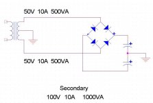
Thanks for the replies, here is a
picture to help me figure out the
mystery.
1KVA secondary, 100v@10A.
Above the center tap, the output
is 50v@10A, below the center tap,
the output is also 50v@10A.
Positive and negative rail voltage,
+50v and -50v.
If I don't use the 'negative' rail
at all, is it possible to get
50v@20A from the positive rail
assuming ideal conditions.
50v@20A = 1KVA since the bottom
1/2 of the transformer is not used,
is this theoretically possible ?
Lets vote
For those who wonder, the answer
I seek is related to this post.
http://www.diyaudio.com/forums/showthread.php?threadid=20878
Attachments
"Lets vote "
You counting wrong answers?
The best I would figure on long term would be an increase in current of 1.414, IOW about 70% of what you could get if you ran the trafo the way it was designed.
Study this:
http://www.amveco.com/Technical_Notes_3.htm
You counting wrong answers?
The best I would figure on long term would be an increase in current of 1.414, IOW about 70% of what you could get if you ran the trafo the way it was designed.
Study this:
http://www.amveco.com/Technical_Notes_3.htm
djk said:"Lets vote "
You counting wrong answers?
The best I would figure on long term would be an increase in current of 1.414, IOW about 70% of what you could get if you ran the trafo the way it was designed.
Study this:
http://www.amveco.com/Technical_Notes_3.htm
Thanks, that works for me. An unsual question that has
some folks scratching the brain

thylantyr said:[snip]If your ideal amplifier is 1000 watts
and you need to design a power
supply, do you need just a 1KVA transformer (500VA per rail)
or do you need a 2KVA
transformer (1KVA per rail)
to supply power to your 1000w amp?
Only one rail operates at any given
moment in time.
[snip]
You have here a hughe safety factor. Unless the amp is used to drive a lamp or something at 1kW constantly, the real output of the amp over time may be no more than 1/10th of that, even with rock music. During the 1kW peaks, it's up to the supply caps to supply the current to the output stage. I mean, the bridge diodes only conduct 10% or so of each mains cycle anyway, so the xformer is effectively disconnected from the amp 90% of the time. Go figure.
Jan Didden
thylantyr said:
If I don't use the 'negative' rail
at all, is it possible to get
50v@20A from the positive rail
assuming ideal conditions.
50v@20A = 1KVA since the bottom
1/2 of the transformer is not used,
is this theoretically possible ?
No, you just would have one 50V@10A transformer. Just think of the transformer of being made of two such transformers connected together with the primary side being capable of delivering 1KVA.
Current is limited by the diameter of the wiring, respectively the generated heat...
If you could cut the center tapping, you could connect the two transformers in parallel. Then you will have one 50V@20A...
Just think of the transformer of being made of two such transformers connected together with the primary side being capable of delivering 1KVA.
Good point, but the two individual transformers would be
designed as such to only allow 500VA each.
The 1KVA example is designed to allow 1KVA, so what
happens to the magnetic flux generated by the primary side ?
Will the top 1/2 of the secondary utilize it if the bottom
1/2 of the transformer is idle ?
janneman - good post, but I'm assuming constant draw
not real world - just to know what is the maximum capability.

thylantyr said:Most amplifiers use a power supply
with a center tapped transformer on
the secondary windings. For example,
let say the transformer is rated for
1KVA, about 100v output with 10 amperes
roughly.
If I use the center tap, I can get
(50v @ 10A = 500VA) * 2 = 1KVA
Hypothetical;
What if I don't use both halves of the
secondary, what if I use only the
50V @ 10A section and don't use
the other half. Can this section
output 50V @ 20A because the other
side is not used ?
If you design a dual rail power supply
with a 1KVA transformer, can I get
1KVA out of each rail when only
one side is used at a time ?
With an ideal transformer yes. In reality no. However if you only need a single output voltage and want to be able to get a supply voltage like you had a single 50V, 20 A winding then use a center tap grounded, full wave rectifier circuit like this.
Please excuse the schematic, I drew it in Viseo and it didn't transfer well.
Phil
Attachments
Phil gets the prize for best way to get 50 v from 100v ct transformer, but you still only get about 95% of the 1kva. His setup still is only using one leg of the transformer (at a time). The smaller wire (compaired to a 50v 20a) causes more resistive heating. One leg of thr transformer could likely produce 40 v 40 a with a short duty cycle. The limit is the temp rise which is dictated by the total average resistive heating. Wire size isn't a signifcant limit to the output current. Put an ohm meter on a 1kva secondary and you'll see around .1 ohms. That's 2v, or 40w (peak) resistive loss.
Originally posted by thylantyr The 1KVA example is designed to allow 1KVA, so what
happens to the magnetic flux generated by the primary side ?
Will the top 1/2 of the secondary utilize it if the bottom
1/2 of the transformer is idle ?
Like written in my posting before, the primary side is capable of 1KVA of course. But the "bottleneck" will be the secondary side. As it is only dimensioned for 500VA you will only get 500VA.
In reality you will be able to get little more than 500VA because the heat in the transformer will be lower like when using it with 1KVA and both secondary windings. So the heat in the single used secondary winding is also a bit lower and so is its resistance. But this will be caused by the different temprature not any magnetic issues.
Primary side of the transformer only delivers the power (source) - secondary side uses this power (drain)...Source will only deliver as much as the drain will need.
When trying to get more than approx. 500VA from one secondary side this side will melt away respectively be shortened while the primary side will just stay fine
If you go to this company you will have information on current ratio between AC current rating of transfo and DC current out of the circuit. The ratio is different if you use a full wave bridge (4 diode circuit 2 outputs) or a full wave centre tap circuit (2 diodes one output)
If you choose to use only 50% of the winding you may go to a higher current but not twice the rated current 141% is probably an honest figure, a current of this value will double the heat production in the part of the winding in use and the unused part will not heat at all.
http://www.atc-frost.com/products/design/va.htm
"Of couse you will have 50V@20A. The power of transformer is the same, 1000W, and is limited by the core section surface and material. If your transformer have a wire large enough (4-5 mm diameter), the loss is negligible. Is like you will rewind the secondary with 1/2."
BAD ANSWER !
Loss in secondary of transformer:
top half at 100% of rating I^2R=1
bottom half at 100% of rating I^2R=1
sum of top and bottom 1+1=2
Double current in top half only I^2R=4
bottom half not driven.
sum of top and bottom 4+0=4
(flaming hot!)
1.414 of nominal current in top I^2R=2
bottom half not driven
sum of top and bottom 2+0=2
While the total heat in the secondary with one half driven at 1.414 times nominal is the same as both halves driven at nominal, hot spots may exist.
The only saving grace here is that the primary current will only be .707 times nominal so there will be some reduction in total temperaure rise.
- Status
- This old topic is closed. If you want to reopen this topic, contact a moderator using the "Report Post" button.
- Home
- Amplifiers
- Solid State
- Transformer question