Hi Everyone.
I'm building the above mentioned amplifier, and there are a few threads mentioning this exact project, but no note of anyone having completed it.
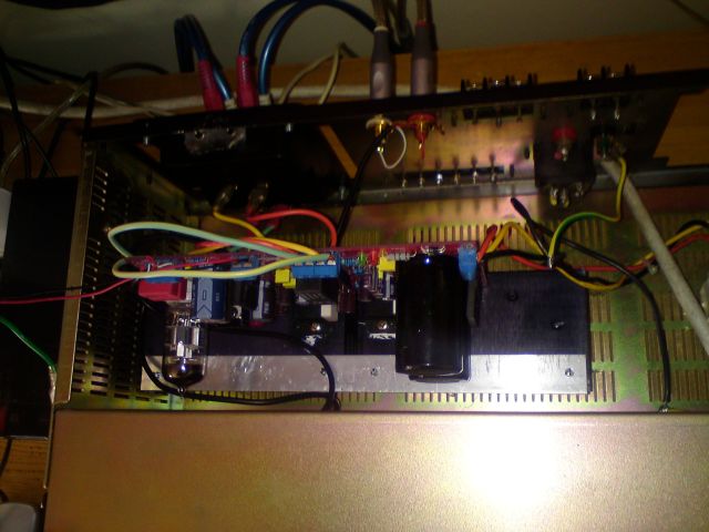
Mine arrived fully assembled; I just had to load the tube and mount the cct onto the heatsink.
I then loaded into a scrap case...
...and made a volume control.
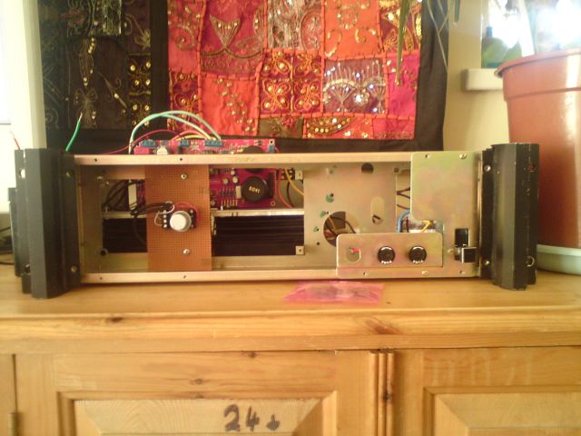
It's still running in, but sounding quite sophisticated at low-ish volumes.
I deffo need a better PSU (currently a 200VA/20-0-20 torroid feeding the on-board caps).
Anyone got a schematic for a 30-0-30@10A DC regulated PSU?
Zennered Darlingtons? Op-amp + Power-stage? AC by-pass caps? Has anyone ever built anything like this before? What's the best design philosophy?
I'm building the above mentioned amplifier, and there are a few threads mentioning this exact project, but no note of anyone having completed it.
Mine arrived fully assembled; I just had to load the tube and mount the cct onto the heatsink.
An externally hosted image should be here but it was not working when we last tested it.
I then loaded into a scrap case...
...and made a volume control.
It's still running in, but sounding quite sophisticated at low-ish volumes.
I deffo need a better PSU (currently a 200VA/20-0-20 torroid feeding the on-board caps).
Anyone got a schematic for a 30-0-30@10A DC regulated PSU?
Zennered Darlingtons? Op-amp + Power-stage? AC by-pass caps? Has anyone ever built anything like this before? What's the best design philosophy?
Okay, so I was having some problems with the 20v transformer; all the expectable ones like no headroom and so on.
So I installed (with some trepidation) the 35v 5A transformer that resided on my test-bench. This had the immediate effect of pushing the speaker protection circuit straight out of it’s comfort zone and into latch-trip-off mode anytime it got pushed past a 6vRMS waveform. So Nurse, board surgery!
First job first, get rid of that awful latch. Option 1 would be to just link-out the output relay, but I kinda like the de-thump delay function, especially with that 6N tube warming-up. So, what controls it? There is a SIL UPC1237 right next door to the relay. The data sheet shows that the latch function is deactivated by an earth on pin three, so link-out C18.
That just left the laughably low level of the trigger. The cct is suppossed to be spec’ed for 68W/ch on a normal heatsink. Mine’s a bit bigger… So, I want to push this thing.
As a start on the trigger-level, with the two 56kRs monitoring the speaker channels summing into a 4u7F electrolytic, I tried a 25% reduction by discharging the 4u7 through a 100kR, but my eyes are getting so bad I got a 180kR instead. So I paralleled that up with another, but realised that it wasn’t transients setting it off, it was sustained bass power. That frequency-dependent characteristic is set by the 4u7.
Therefore, ultimate mod; stick a 10uF across that.
Job done. Now I can get 80w/ch out of it. Seriously, even the smoothing cans get warm. Never seen that before…
I´m about to order this amp. What makes you think this needs a bigger trafo. The seller (along......) claims that a 150va 24-0-24 0-9 (that he also sells) is enough.
Do you have another gainclone to compare with?
Sound quality, detail, bass, etc.
RGDS
PEMO
")
Hi Pemo.
It's Coke; I'm lovin it.
The bass is really good now; deep, tuneful. My mate Kev said it was " a thumpy piece of kit".
It really holds female vocals well; Eva Cassidy doing fields of gold had my friend Alison in floods of tears.
So, that's a 9 and a 9, and a 8.5 for stereo imaging. I still think it needs a firmer power supply (think; Point of Diminishing Returns).
There are some further details of the build on there as well.
http://alacrityaudio.co.uk/2012/03/09/scrap-lifier-project-pics/
http://alacrityaudio.co.uk/2012/03/09/scrap-lifier-project-pics/
Last edited:
Haha, sweet! Looking forward to seeing what else you do with it, the 10uF cap mod seems pretty great. What transformer do you think will work with a regular sized heatsink? I might have a larger one lying around too, so I might emulate your setup a little. Also, bought it!
Haha, sweet! Looking forward to seeing what else you do with it, the 10uF cap mod seems pretty great. What transformer do you think will work with a regular sized heatsink? I might have a larger one lying around too, so I might emulate your setup a little. Also, bought it!
Nice one, nullbyte.
I'd have been happier trying a 30/0/30 200va first; that might not have tripped-out the speaker-protect, but I'm happy with the sound at 35/0/35.
Let me know if you face any problems.
One last time, to be clear. Link across C18 to disable trip-latch-off, then take C19 up to 15uF to avoid triggering the speaker-protection circuit.
 WORDS OF CAUTION. THESE ACTIONS MAY VOID YOUR WARRANTY!!!
But in my case, I don't care.
What I like is that I've got a piece of kit that now scares me before I break it.
Is that 30-0-30 ac and 35-0-35 ac?
If yes, the LM3886 and 4780 peek to peek is supposed to be maxed at 80Vdc max...
30Vac = +/- 42Vdc and 35Vac = +/- 50Vdc which would bring you to 84Vdc and 100Vdc respectively on 120Vac or 240Vac primaries...
I guess you're playing with fire here...
I bought a PCB and stuffed it myself. It is running two LM4780 with an X10 buffer. Sounds really good but the LM4780 seem to be oscillating since they get pretty hot quickly... And the heatsink is way adequate... I've been looking at the 4780 spec sheet on what to do in that case but have not implemented anything yet...
Here it is
Every single parts in there is good quality and sourced through Mouser. Digikey and Parts Connexion.
If anyone is interested in fixing it (I don't have time, too many projects right now), just PM me!
Ciao!
Do
If yes, the LM3886 and 4780 peek to peek is supposed to be maxed at 80Vdc max...
30Vac = +/- 42Vdc and 35Vac = +/- 50Vdc which would bring you to 84Vdc and 100Vdc respectively on 120Vac or 240Vac primaries...
I guess you're playing with fire here...
I bought a PCB and stuffed it myself. It is running two LM4780 with an X10 buffer. Sounds really good but the LM4780 seem to be oscillating since they get pretty hot quickly... And the heatsink is way adequate... I've been looking at the 4780 spec sheet on what to do in that case but have not implemented anything yet...
Here it is
An externally hosted image should be here but it was not working when we last tested it.
An externally hosted image should be here but it was not working when we last tested it.
Every single parts in there is good quality and sourced through Mouser. Digikey and Parts Connexion.
If anyone is interested in fixing it (I don't have time, too many projects right now), just PM me!
Ciao!
Do
Last edited:
Is that 30-0-30 ac and 35-0-35 ac?
If yes, the LM3886 and 4780 peek to peek is supposed to be maxed at 80Vdc max...
30Vac = +/- 42Vdc and 35Vac = +/- 50Vdc which would bring you to 84Vdc and 100Vdc respectively on 120Vac or 240Vac primaries...
I guess you're playing with fire here...
I bought a PCB and stuffed it myself. It is running two LM4780 with an X10 buffer. Sounds really good but the LM4780 seem to be oscillating since they get pretty hot quickly... And the heatsink is way adequate... I've been looking at the 4780 spec sheet on what to do in that case but have not implemented anything yet...
Here it is
An externally hosted image should be here but it was not working when we last tested it.
An externally hosted image should be here but it was not working when we last tested it.
Every single parts in there is good quality and sourced through Mouser. Digikey and Parts Connexion.
If anyone is interested in fixing it (I don't have time, too many projects right now), just PM me!
Ciao!
Do
Sweet, seperate tube buffers, high power output stage... whats not to like?
I think my meter is an auto-RMS; the DC is 35 across the caps!
And is yours oscillating, or are they passing Res-Cap-drained-rectified-DC?

Hey copperweed,
I'm not getting the last part of this
Thanks!
Do
I'm not getting the last part of this
And is yours oscillating, or are they passing Res-Cap-drained-rectified-DC?
Thanks!
Do
"I guess you're playing with fire here... "
Um, yeah, that's my job.
Give me an envelope...
Hi copperweed,
Not familiar with that expression... Sorry if I have insulted you.
Do
Hi copperweed,
Not familiar with that expression... Sorry if I have insulted you.
Do
Not insulted at all. I admit I was pushing the SOAR envelopes of the chips. I'd be happier if it was 30/0/30 volts.Hey copperweed,
I'm not getting the last part of this
Thanks!
Do
Sometimes, if the output stage has gone short-circuit, it can sound like it's oscillating at 50 or 60 Hz. The power has been transformered, rectified and smoothed, but then, if the smoothing caps are shorted to ground through the speakers, it can sound like a full-power oscillation. I need to know aprox frequency to be sure. Whistling or whining could be osc., but loud buzzing could be a blown chip.
Hi Copperweed, what do you think about the PSU is it enough. Are the caps big enough?
RGDS
PEMO
Hi Pemo.
When it's loud (like, 75/80wpch), there is some compression, but if I had a regulated 30/0/30Vdc PSU @ 10A, or even 35/0/35 @ 10A, instead of a Tx on the end of the supply chain then I'd be a lot more satisfied.
You just CAN'T HAVE too much power supply...

- Status
- This old topic is closed. If you want to reopen this topic, contact a moderator using the "Report Post" button.
- Home
- Amplifiers
- Solid State
- Hybrid DIY cct of LM3886+6N11