I have a powered subwoofer (Sony; please don't laugh, it's just for the workshop) and would like to add a line out to it from a chipamp I'm building (ESP preamp to 2x TDA2050s).
I've read the Rane article "Why not Wye?" about adding a passive summer to your inputs and built a stereo-to-mono unit in a small Radio Shack project box.
It works well, even considering the 27 dB crosstalk (not that I'd notice down here in the 'shop).
However, that got me thinking...
How about an active summer that wouldn't load the inputs AND avoid the crosstalk issue?
I wanted it simple with a minimum of parts so it could easily be added as a small PCB to a commercial unit or built into a diy board, and high-impedance to avoid loading the inputs as much as possible.
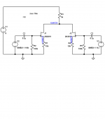
Here's my circuit; it's 2 FETs (for high-Z input; low loading) wired source-follower (for low output Z and maintained phase) with shared source resistor.
Works well in LTSpice simulation, and I wanted to run it by you folks before I blow something up with it.

Questions? Comments? Suggestions?
Thanks.
-Eddy
P.S. No low-pass on the output because my powered sub already has a crossover.
I've read the Rane article "Why not Wye?" about adding a passive summer to your inputs and built a stereo-to-mono unit in a small Radio Shack project box.
It works well, even considering the 27 dB crosstalk (not that I'd notice down here in the 'shop).
However, that got me thinking...
How about an active summer that wouldn't load the inputs AND avoid the crosstalk issue?
I wanted it simple with a minimum of parts so it could easily be added as a small PCB to a commercial unit or built into a diy board, and high-impedance to avoid loading the inputs as much as possible.
Here's my circuit; it's 2 FETs (for high-Z input; low loading) wired source-follower (for low output Z and maintained phase) with shared source resistor.
Works well in LTSpice simulation, and I wanted to run it by you folks before I blow something up with it.
Questions? Comments? Suggestions?
Thanks.
-Eddy
P.S. No low-pass on the output because my powered sub already has a crossover.
Try your sim again...My impression was that it would have bad intermodulation problems...I did a tran sim, with 0.5 volts of 100 Hz in one input, and 1 volt of 1 kHz in the other...the results were quite non-linear...
Hmm... hadn't thought of that.
So without a low-pass going IN, I'd likely get intermodulation artifacts dirtying up the output, right?
Just sim'd it, very interesting output that I don't remember getting before. Did you get something like this?
Blue=1kHz / Green=100Hz / Red=Output
I imagine it'd do something different with actual music, rather than reference signals, but still that looks scary.
I also sim'd the passive mono-to-stereo circuit from the 'Why not Wye' article, and it looks like you'd expect; a 1000Hz signal modulated by 100Hz.
Maybe I should either live with the crosstalk, or come to grips with the fact that an active stereo-to-mono circuit just isn't as simple as it seems.
So without a low-pass going IN, I'd likely get intermodulation artifacts dirtying up the output, right?
Just sim'd it, very interesting output that I don't remember getting before. Did you get something like this?
An externally hosted image should be here but it was not working when we last tested it.
Blue=1kHz / Green=100Hz / Red=Output
I imagine it'd do something different with actual music, rather than reference signals, but still that looks scary.
I also sim'd the passive mono-to-stereo circuit from the 'Why not Wye' article, and it looks like you'd expect; a 1000Hz signal modulated by 100Hz.
Maybe I should either live with the crosstalk, or come to grips with the fact that an active stereo-to-mono circuit just isn't as simple as it seems.
Last edited:
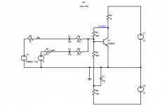
yes...your sims look like mine. You wouldn't have to add a lot to make it much more linear, and cut the crosstalk...I'll keep with your theme, just change it a little bit...(see enclosed pic). This version inverts, take output at the common drains through a coupling cap.
Alternatively, You can also use 1 opamp, and make a summer...owing to the virtual ground, it wouldn't cause crosstalk between the channels.
Alternatively, You can also use 1 opamp, and make a summer...owing to the virtual ground, it wouldn't cause crosstalk between the channels.
Attachments
Your idea worked out well in the simulation, i would just swap 5k's at sources and a 10k for the drain so the DC operating point at the drain is ~1/2 the voltage (give or take).
Drop the voltage to 12V, and it's 5k all 'round.
I had originally went with the source-follower circuit because it would give low output impedance and doesn't amplify; that's what the powered sub is for.
This configuration has a higher output impedance and just a touch of gain; not much at those values and without bypass caps at the sources, but it's there, and needs to be taken into consideration.
I also didn't want to go with an op-amp because it was a more complicated circuit, and there was still the issue (so I thought) of cross-talk.
Can you recommend a simple op-amp circuit?
Or maybe I just need to wire these things up and give it a listen.
I doubt I'm going to blow anything up, and prolly learn a thing or two in the process.
Common drain (=source follower) does not invert.
Common source does invert and amplify.
You can use common source to invert and sum at it's input.
Just set the gain as low as you can and still maintain stability.
edit:
Now I am having second thoughts!
Does a single transistor in common source/emitter sum at it's input?
Common source does invert and amplify.
You can use common source to invert and sum at it's input.
Just set the gain as low as you can and still maintain stability.
edit:
Now I am having second thoughts!
Does a single transistor in common source/emitter sum at it's input?
Last edited:
Here's a summer, based not on an opamp, but a 1 transistor version thereof, which I like to call a "slop-amp". It doesn't have as much gain as an opamp, but works in a similar fashion. Left and Right are the outputs of left and right preamp signals...you'll see that the crosstalk (left signal appearing on the right undriven output) is -73 dB. The output of the summer is at the collector of the transistor
Attachments
Hi,
Its far simpler to make an entirely passive mixer
driven from the output of the chip, its 3 resistors.
Say 2x1K and 50R.
rgds, sreten.
Its far simpler to make an entirely passive mixer
driven from the output of the chip, its 3 resistors.
Say 2x1K and 50R.
rgds, sreten.
A passive mixer was what I learned and used from Rane's "Why not Wye" article, and I must admit it did work well enough for the workshop system.
BUT... the closet audiophile in me that just knew there was 27dB of crosstalk going on, --even if I couldn't hear it--, was always nagging me, so I thought I'd try to come up with a simple active solution because that would eliminate crosstalk and loss; of course, at the expense of a large degree of simplicity, but also allowing a low-impedance output which is, in my mind, always a good thing.
So, to clarify, I'm trying to design the simplest circuit possible that not only sums to mono for my sub, but isolates the two inputs.
Djoffe, your first circuit seems to fit the bill; it matches the type of signal that would come out of passive mixing, but with maximum isolation.
Perhaps an improvement would be adding a third FET or even a transistor as a source/emitter follower to buffer the first stage and provide low-impedance output for good measure, and it would only require two more parts.
I'll post a circuit and sim results later today...
OK, here's a final circuit, only 3 more parts than the original.
As with all JFETs, the drain resistor may need tweaking for optimal sound, especially with different voltages, as noted on the schematic.
2N3819s and MPF102s were used in simulation and provided very similar results.
J201s and 2N5457s gave very different results, YMMV.
As with all JFETs, the drain resistor may need tweaking for optimal sound, especially with different voltages, as noted on the schematic.
2N3819s and MPF102s were used in simulation and provided very similar results.
J201s and 2N5457s gave very different results, YMMV.
An externally hosted image should be here but it was not working when we last tested it.
Last edited:
Assume the inputs are called VinLeft and VinRight. The output is then
Vout=-k*(VinLeft+VinRight), where k is a positive number.
Thus, I'd call it a summer with a phase inversion.
That phase inversion can be dealt with, if needed, by swapping the leads on the sub-woofer.
Vout=-k*(VinLeft+VinRight), where k is a positive number.
Thus, I'd call it a summer with a phase inversion.
That phase inversion can be dealt with, if needed, by swapping the leads on the sub-woofer.
Would inputting two in phase signals to the inputs result in twice the voltage at the output and the output inverted relative to the two inputs.
Yes...for example...
If driving a single input with a 100 mV signal produced 103 mV at the output, then driving both inputs with 100 mV in phase signals would produce 206 mV at the output. In both cases, the input(s) and the output would be out of phase.
If driving a single input with a 100 mV signal produced 103 mV at the output, then driving both inputs with 100 mV in phase signals would produce 206 mV at the output. In both cases, the input(s) and the output would be out of phase.
Good points, and a new thought; since most bass signals tend to be monophonic, the result would be a bass boost before sending off to the sub (could be good, could be bad).
Perhaps R6 should be a trimmer or small potentiometer, to adjust levels back down before being output if it's a problem.
Perhaps R6 should be a trimmer or small potentiometer, to adjust levels back down before being output if it's a problem.
OK, I totally missed this one, but Djoffe, your "slop-amp" should work just fine, and now I know why.
According to this ESP article, even though the inputs are connected, there is no crosstalk because the connection point at the junction of input and feedback loop is a virtual earth for the input signals.
Audio Signal Mixing
One of those 'light bulb above your head' moments...
According to this ESP article, even though the inputs are connected, there is no crosstalk because the connection point at the junction of input and feedback loop is a virtual earth for the input signals.
Audio Signal Mixing
One of those 'light bulb above your head' moments...
- Status
- Not open for further replies.
- Home
- Amplifiers
- Solid State
- Simple subwoofer buffer/summer circuit