Hello
I want to simulate this SG3524 inside schematic with LTspice or Tina-Ti, but there is parts that I can't identify, it's Q6 and Q58, R6 and R40, we can see few others similar parts in the schematic.
Can you tell me what are those parts and if I can use a combination of standard bjt transistors to do an equivalence of Q6 and Q5 ?
I include images of those parts, the SG3524 inside schematic and the SG3524 block diagram.
Thank
Bye
Gaetan
Attachments
Last edited:
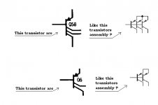
think of the transistor with multiple collectors as multiple transistors where base and emitters are common, but the collectors are separate.
The resistors with the lines are still resistors, although they're usually made in a way that has a fairly high voltage coefficient, so the circuits typically make use of matching, or the resistors being rather uncritical in their value.
The resistors with the lines are still resistors, although they're usually made in a way that has a fairly high voltage coefficient, so the circuits typically make use of matching, or the resistors being rather uncritical in their value.
think of the transistor with multiple collectors as multiple transistors where base and emitters are common, but the collectors are separate.
Hello
Is it like in the image I include ?
Thank
Bye
Gaetan
Attachments
Hello
So, R6 resistor do just have a center tap ?
Thank
Bye
Gaetan
No that could be the back connection. An n+ resistor is made with emitter matierial and has a base emitter breakdown possible so you must take care in connecting the back (p) to a potential that avoids this or they are pinch resistors which are like FETs operated in triode region where that little bar is the "gate". Very nonlinear but the only way to easily get high value resistors in olden times but are still used in some places. The comment about the multi-collector pnp's is correct exccept that they can have high level injection and there is a parasitic collector to the substrate, best to just use the parallel devices and hope for the best.
http://www.mos-ak.org/montreux/posters/12_Banas_MOS-AK06.pdf
Last edited:
No that could be the back connection. An n+ resistor is made with emitter matierial and has a base emitter breakdown possible so you must take care in connecting the back (p) to a potential that avoids this or they are pinch resistors which are like FETs operated in triode region where that little bar is the "gate". Very nonlinear but the only way to easily get high value resistors in olden times but are still used in some places. The comment about the multi-collector pnp's is correct exccept that they can have high level injection and there is a parasitic collector to the substrate, best to just use the parallel devices and hope for the best.
http://www.mos-ak.org/montreux/posters/12_Banas_MOS-AK06.pdf
Hello Scott
In my LTspice simulation, can I replace all those n+ resistor by standard resistors of sames values, if not, what can I use ?
And in my LTspice simulation, I will replace all the multi-collector pnp's by parallel devices.
Thank you
Bye
Gaetan
Last edited:
- Status
- This old topic is closed. If you want to reopen this topic, contact a moderator using the "Report Post" button.
- Home
- Amplifiers
- Solid State
- Need to identify unknow parts in a IC schematic