First, I am (was) a kit builder. I therefore have limited skill and knowledge. When I am guided I do well with repairs and can solder fairly well.
I have a Hafler DH 101 preamp I built that and later modified with a kit from Musical Concepts. The modified preamp sounded great! At some point I rec'd a Tandberg amp/preamp/tuner (3000 series) from a friend and the DH 101 was largely relegated to a shelf. I would bring it out from time to time and recently repaired the plastic strip holding the RCA jacks.
Yesterday I decided to hook it up for my son to use and discovered something is wrong. It plays but the sound is distorted. At first I thought it might be blown speakers but I have determined it is the preamp. It sounds very much like blown speakers or a partially blown inline power amp fuse. The distortion seems spread throughout the audio spectrum and is exacerbated as the volume is increased. It sounds "overdriven".
I'm stuck as I have no idea what might cause this and do not have the technical skill to trace the problem.
Is there anything I can do to repair this myself or is it time to sell to someone with the skill to repair. Any obvious possibilities come to mind? It is such a great sounding little preamp and it has sentimental value to me, I'd love to be able to repair it but can't put too much money into it. It would probably be a steal for someone on Ebay that could repair it.
I appreciate your guidance.
Last edited:
Hi,
Do you have a voltmeter? If so, the first place to start would be the power supply. With your voltmeter negative lead on pin 10 of each amplifier board in turn (labelled PC-4), measure the voltage on pin 12 (+18V) and then pin 11 (-18V). I suspect it's a supply problem if the distortion is present on both channels.
Do you have a voltmeter? If so, the first place to start would be the power supply. With your voltmeter negative lead on pin 10 of each amplifier board in turn (labelled PC-4), measure the voltage on pin 12 (+18V) and then pin 11 (-18V). I suspect it's a supply problem if the distortion is present on both channels.
I don't have a voltmeter but I can borrow one. Assuming it is the power supply (as determined by testing for the voltages you described) what would the next step be? I recognize this is a bit of a silly question, but at that point does one replace the entire supply or is there a likely component(s) needing replacement?
I have seen this Ebay kit to upgrade the DH 101 power supply, but my concern is that my preamp has already been upgraded by Musical concepts and I don't know how this kit might integrate with an already modified one. I wish I was a little more proficient in this arena.
I have seen this Ebay kit to upgrade the DH 101 power supply, but my concern is that my preamp has already been upgraded by Musical concepts and I don't know how this kit might integrate with an already modified one. I wish I was a little more proficient in this arena.
I don't have a voltmeter but I can borrow one. Assuming it is the power supply (as determined by testing for the voltages you described) what would the next step be? I recognize this is a bit of a silly question, but at that point does one replace the entire supply or is there a likely component(s) needing replacement?
I have seen this Ebay kit to upgrade the DH 101 power supply, but my concern is that my preamp has already been upgraded by Musical concepts and I don't know how this kit might integrate with an already modified one. I wish I was a little more proficient in this arena.
If there is a fault in the supply, the next step would be to determine which components have failed and replace them as necessary. From the age of the kit, ~1978 according to the manual, it would be a very good idea to replace all of the electrolytic capacitors as the originals would most likely have dried out by now. A few measurements with a voltmeter should help pinpoint the problem.
Would using a kit like this be good place to start if one assumes age dictates wholesale replacing older parts?If there is a fault in the supply, the next step would be to determine which components have failed and replace them as necessary. From the age of the kit, ~1978 according to the manual, it would be a very good idea to replace all of the electrolytic capacitors as the originals would most likely have dried out by now. A few measurements with a voltmeter should help pinpoint the problem.
Would using a kit like this be good place to start if one assumes age dictates wholesale replacing older parts?
I would take some measurements before doing anything else. There is no guarantee that this kit would fix the problem, although it might be useful to have for spares, if you were so inclined. Only when you have located the fault will you know a) whether it is worth repairing and b) what it might cost.
Yes, I'm sure you're correct on that. I shouldn't look for a "quick fix" until I know what's brokenI would take some measurements before doing anything else. There is no guarantee that this kit would fix the problem, although it might be useful to have for spares, if you were so inclined. Only when you have located the fault will you know a) whether it is worth repairing and b) what it might cost.
") . Frankly, I just don't know what to test other than the 2 areas you described...... Step one is securing a voltmeter.
. Frankly, I just don't know what to test other than the 2 areas you described...... Step one is securing a voltmeter. Here is an important question, I assume all measurements with the voltmeter are made with the preamp unplugged from power? I would be quite hesitant to be tinkering in a powered up unit.
Yes, I'm sure you're correct on that. I shouldn't look for a "quick fix" until I know what's broken
Here is an important question, I assume all measurements with the voltmeter are made with the preamp unplugged from power? I would be quite hesitant to be tinkering in a powered up unit.
As you will be taking voltage measurements, power must be applied so you will need to exercise caution, taking care to protect yourself and not to accidentally short out anything in the process with the meter probes. If there are exposed mains terminals within the pre-amp, position the case such that you don't have to lean or reach across these areas while it is powered up as you take your measurements. If you are uncertain, would you be able to post a photo of the inside from above?
This pre-amplifier had a ground-loop problem -- easy to remedy. There's been a post on the unit that addresses the problem: http://www.diyaudio.com/forums/analogue-source/203757-dh-101-noisy-phono-stage-3.html
As you will be taking voltage measurements, power must be applied so you will need to exercise caution, taking care to protect yourself and not to accidentally short out anything in the process with the meter probes. If there are exposed mains terminals within the pre-amp, position the case such that you don't have to lean or reach across these areas while it is powered up as you take your measurements. If you are uncertain, would you be able to post a photo of the inside from above?
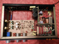
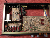
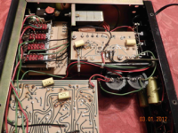
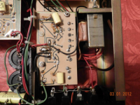
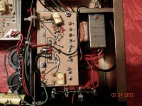
Here are some pics:
* They are pretty small. I couldn't seem to upload any of the larger .jpg files even though they were within the size limitations.
Attachments
Last edited:
If it hasn't been used in a long time, clean all switches and controls first.you would be surprised by the amount of corrosion that can build up on on switch and volume control contacts without constant use. Usually the plating on contacts sometimes lasts through warranty. I may be skeptical, but I live on the east coast of Florida, one of the most corrosive environments in the world.
Hi,
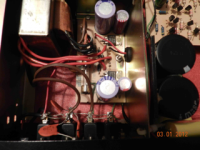
Thanks for the photos. The 5th picture would be most the appropriate, which shows the rear of the power supply regulator board. If you positioned the unit exactly as shown in this photo in front of you, you can probe various points on the back of this board. The rear of the unit is now facing you. Remove any rings and metal watch straps, if present.
Select a voltmeter range to read DC voltages of at least 30V. Switch on the pre-amp. Place the black probe on ground point 11.
Place the red probe on the upper connection of the yellow capacitor nearest you (C25). This should read approximately -27V DC.
Move the red probe only to the lower connection of the upper yellow capacitor (C24). This should read approximately +27V DC.
Move the red probe only to point "3". This should read approximately -18V DC.
Move the red probe only to point "12". This should read approximately +18V DC.
This will verify the output of your power supply.
Thanks for sticking with me on this. I do appreciate it. I still need to acquire a voltmeter so it may be a little bit before I respond back. I did post larger views of the pictures above here.Hi,
Thanks for the photos. The 5th picture would be most the appropriate, which shows the rear of the power supply regulator board. If you positioned the unit exactly as shown in this photo in front of you, you can probe various points on the back of this board. The rear of the unit is now facing you. Remove any rings and metal watch straps, if present.
Select a voltmeter range to read DC voltages of at least 30V. Switch on the pre-amp. Place the black probe on ground point 11.
Place the red probe on the upper connection of the yellow capacitor nearest you (C25). This should read approximately -27V DC.
Move the red probe only to the lower connection of the upper yellow capacitor (C24). This should read approximately +27V DC.
Move the red probe only to point "3". This should read approximately -18V DC.
Move the red probe only to point "12". This should read approximately +18V DC.
This will verify the output of your power supply.
(The link is kind of funny, I must have once called the folder "tempAtari" when I was working on an old 1040 st) Oh well...the new pics are there now.
Also, I did find the original documents that came with the kit originally and the instructions that came with the Musical Concepts mod. Maybe that will be helpful at some point. Thanks again
> some pics:
Find kit manual; it has some basic troubleshooting.
Get voltmeter. Put on DC Volts. (50V or 200V range if not auto-ranging.)
First take a 9V battery and poke it with the voltmeter. You should get around 9v reading. If you flip the black and red probes on the small and large terminals, one way there should be a "-" sign in the display.
Hafler away from kids, open, plugged-in, turned-on.
BEWARE the backs of the accessory wall-outlets!!
Voltmeter black wire to chassis.
Probe the two large capacitors shown. Do you get these voltages? ("25V" may be 21V or 30V; we are looking for very-wrong values, not exact values.) (It is possible these caps are the +/-15V storage; if they are same-Voltage opposite polarity then that's probably OK.) (The manual may show correct voltages.)
Attachments
Last edited:
Thanks for sticking with me on this. I do appreciate it. I still need to acquire a voltmeter so it may be a little bit before I respond back. I did post larger views of the pictures above here.
(The link is kind of funny, I must have once called the folder "tempAtari" when I was working on an old 1040 st) Oh well...the new pics are there now.
Also, I did find the original documents that came with the kit originally and the instructions that came with the Musical Concepts mod. Maybe that will be helpful at some point. Thanks again
The original documents will come in useful, although I found what appears to be the original construction manual on the manufacturer's web site. Good luck with your measurements
Here is a picture of the meter I borrowed. Does it seem like it will work? It is old and appears to be analog, but he says it works fine. I added larger picks with the others here.
Attachments
Last edited:
Here is a picture of the meter I borrowed. Does it seem like it will work? It is old and appears to be analog, but he says it works fine. I added larger picks with the others here.
yes, it will work just fine! put it on 125v "DC" mode and start doing some readings.
But, as mentioned before clean all contacts using "tuner cleaner" spay.
WARNING! you are going to work with live voltages... Be careful!
Have I identified everything correctly in the pic? Am I correct that my meter requires reversing probes to determine negative voltage?Hi,
Thanks for the photos. The 5th picture would be most the appropriate, which shows the rear of the power supply regulator board. If you positioned the unit exactly as shown in this photo in front of you, you can probe various points on the back of this board. The rear of the unit is now facing you. Remove any rings and metal watch straps, if present.
Select a voltmeter range to read DC voltages of at least 30V. Switch on the pre-amp. Place the black probe on ground point 11.
Place the red probe on the upper connection of the yellow capacitor nearest you (C25). This should read approximately -27V DC.
Move the red probe only to the lower connection of the upper yellow capacitor (C24). This should read approximately +27V DC.
Move the red probe only to point "3". This should read approximately -18V DC.
Move the red probe only to point "12". This should read approximately +18V DC.
This will verify the output of your power supply.
Attachments
I reverse the probes on my meter to make the negative measurements right?> some pics:
Find kit manual; it has some basic troubleshooting.
Get voltmeter. Put on DC Volts. (50V or 200V range if not auto-ranging.)
First take a 9V battery and poke it with the voltmeter. You should get around 9v reading. If you flip the black and red probes on the small and large terminals, one way there should be a "-" sign in the display.
Hafler away from kids, open, plugged-in, turned-on.
BEWARE the backs of the accessory wall-outlets!!
Voltmeter black wire to chassis.
Probe the two large capacitors shown. Do you get these voltages? ("25V" may be 21V or 30V; we are looking for very-wrong values, not exact values.) (It is possible these caps are the +/-15V storage; if they are same-Voltage opposite polarity then that's probably OK.) (The manual may show correct voltages.)
I reverse the probes on my meter to make the negative measurements right?
Yes..
Before you start temporarily cover the primary lugs on the transformer with electrician's tape and do the same with the accessory outlets (backside), fuse and power switch. This will reduce the likelihood of an accident in the event of inadvertent contact with one of those points. Exercise caution, these temp fixes are only meant to reduce risk, they will not eliminate it. Be careful! You'll get the hang of it, and it sounds like you don't take safety for granted so you will be OK.
A DMM would be a more useful tool for trouble shooting, and decent cheap ones are available on eBay.
- Status
- This old topic is closed. If you want to reopen this topic, contact a moderator using the "Report Post" button.
- Home
- Amplifiers
- Solid State
- Hafler DH 101 last ditch effort