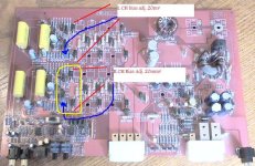
For those of you who are unfamiliar with this amp, this was a high end SQ car audio amp from the 90's that was marketed as being class A. Previous amps from the company were actually high biased class a/b amps. Until recently I thought the same of this amp. Recently AZVRT sent me some instructions on how to bias this amp, the attached photo is a 2 channel version of the same amp. When I went to check the bias, it was set ~ 40mv instead of 20mv on each channel. AZVRT was informed that this amp should never be biased more then 20mv as it could damage the amp. Considering that 20mV is .01A bias I would think that you could bring this quite a bit higher. As it sits now, the amp does not even warm up while being used. From looking at the schematic do you guys see any problem with bringing the bias higher? What if I wanted to bias it completely into class A?
I was also wondering if you guys see any mods that might improve the design. I know I could replace the opamps but I am not sure that will have much of an impact on the sound. I see there are two caps on the input, could someone tell me why there is two? I am assuming one of them is there to block DC but I am not sure. If so, could I bypass it? I understand I would be susceptible to DC then but I may be willing to take that risk.
Here is a link so you can see the amp and it's heat sink.
SoundStream Reference Class A Picasso
Attachments
you cannot bias it in classA due to very small heatsink.
For class A you must have a HUGE heatsink.
Those Soundstream are classAB with diodes+resistors instead of simple emitter resistors. This means that transistor's shut off is soft..but it's always a classAB topology.
You can rise the bias, but the amplifier will heat quickly and goes on thermal runaway if bias isn't perfectly set.
If you want to mod it, look ad the opamp section for example. The results may be interesting")
For class A you must have a HUGE heatsink.
Those Soundstream are classAB with diodes+resistors instead of simple emitter resistors. This means that transistor's shut off is soft..but it's always a classAB topology.
You can rise the bias, but the amplifier will heat quickly and goes on thermal runaway if bias isn't perfectly set.
If you want to mod it, look ad the opamp section for example. The results may be interesting
Is thermal runaway the only problem with raising the bias?
I am using this amp on a pair of DE500+image dynamics horn bodies. I want to try to keep the amp in class A mode for at least the first 5 watts, is that reasonable?
The heatsink is 16"X8"X3/4", wouldn't that be enough to bring the bias up on 2 of the channels? It would be equivilent to 2 of these (4.230" Wide x 16" Long Heatsink - HeatsinkUSA, LLC Store), I would think that should be able to dissipate quite a bit of heat.
I was told that changing the opamps had little effect on the sound of this amp. I would try that first if I had heard otherwise.
Thermal runaway is the main problem (and the heatsink temperature).
For 5W @4ohm you've to rise the bias to 150mA each output transistor.
You will not hear so much differences from now. That bias affect only the mid-high distortion. Not easy to hear.
Opamps make more differences in the sound.
For 5W @4ohm you've to rise the bias to 150mA each output transistor.
You will not hear so much differences from now. That bias affect only the mid-high distortion. Not easy to hear.
Opamps make more differences in the sound.
The drivers are 8 ohm and I have them playing 1.5k and up so I am guessing that it might make a difference.
I think I might try to bring up the bias and see what happens, I didn't pay a lot for the amp so it might be with trying.
If that does improve the sound, the next step will be opamps.
I think I might try to bring up the bias and see what happens, I didn't pay a lot for the amp so it might be with trying.
If that does improve the sound, the next step will be opamps.
You can always use a fan to further cool the heatsink.
So if you want to raise the bias a lot, do it. But I was warned against doing it for a technical reason other than the amp heating up. I think some transistors will die, not sure what it was.
I replaced the OP275 by sockets on this amplifier and tried OPA2134, OPA2227, OPA2604, OPA2107, LME49720 and probably more that I cannot remember right now. I did not hear any difference. I thought I did, but with back to back testing and making sure I was sitting in the same position in the room, I could detect no difference.
My father thought he heard huge differences between op-amps A and B. So at some point I put in A, removed A and put A back in while he thought B was in and he confirmed op-amp B really sounded different, while A was still in. That´s my experience, put a lot of money in this op-amp test with zero results (my opinion).
I did the same test on several amplifiers, with OPA627, OPA404, LME49740, LME49710 and many many others, nothing.
Amplifiers do sound very, very different in my opinion, but after my experiment I don´t believe the op-amps are the cause of this.
I asked a former car amplifier manufacturer for you, this is what he said:
"The bias sense transistor is located on the heatsink some distance from the outputs.
If the amp is run hard then the outputs get hotter than the heatsink and the bias current rises accordingly.
It takes a while for the heatsink to heat up so the bias can continue rising and cause thermal runaway popping either the fuse or an output device.
Our (other brand than Soundstream) sense transistor is mounted on the output device tab and senses the output device temperature directly which responds about 30 times faster, so tracks the bias much better.
You can move the bias transistor on SS amps to the nearest output device tab if the outputs are TIP102 / TIP107.
It's harder on the higher spec amps as they use bigger package parts without an exposed tab, though these have a smaller temp rise issue compared with the 102 / 107 equipped amps.
Hope this helps. I have also asked a former SS employee, will let you know once I get a reply.
That is what I was thinking the problem might be. Thanks for looking into if for me. I have decided to leave the amp be for now. If I decided to bring up the bias, it will only be on the horn driver channels and I am going to wait for summer to get here before I mess with it.
It seems that if you fan-cool the amp you might be able to turn up the bias a little further.
Keep in mind that the current demand of higher frequencies is very, very little.
If you could make your amp idle at 1.5 ampere, the current demand might never exceed the idling current.
For instance, my Ref Picasso drives 4 tweeters on a pretty high high-pass. I don't believe the current demand ever exceeds the 1.4 ampere idling current, so turning up the bias would be pretty useless in my case, I believe.
So today I decided to up the bias to ~ 95mV on 2 channels of the amp. I am using these 2 on my horns only so the load is low. I am not using the other 2 channels currently. After playing with the amp for over an hour it was just warm to the touch. I would crank the bias up higher but the pots limit it to ~115mv and I am not sure I will see much difference between 95 and 115mV. I will keep this updated if I run into any other problems or make any other changes.
Hi,
I would be interested to know the idle current.
How much mvdc are the other 2 channels set to ?
What would be really interesting is if you'd set 2 channels to the original 20 / 25 mvdc and the others to 95 mvdc and have someone perform a blind test on you, several times.
I wonder whether any difference could be heard, in reality.
Best regards,
Fred
- Status
- This old topic is closed. If you want to reopen this topic, contact a moderator using the "Report Post" button.
- Home
- Amplifiers
- Solid State
- Soundstream Picaso - Bias and mods question