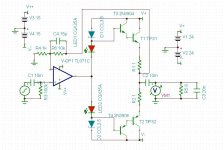
This one makes about 4.5 watts into 8 ohms @ 0.06% distortion (1kHz, 800mV p-p input), according to simulation.
It may (or may not
") ) work but 4.5 watts from a multirail amp that needs -/+ 35 volts for one set of rails... it's a non starter.
) work but 4.5 watts from a multirail amp that needs -/+ 35 volts for one set of rails... it's a non starter.It may (or may not
It probably doesn't NEED +/- 35 volts. I didn't investigate that. It's just something I threw together using his components and basic topology. Maybe you should do something and figure it out yourself.
And, about the input. A cap impedance is inversaly proportional at the sound frequency. It's a series cap. when hi freq came, they pass more easily then low freq, wich should mean this is a "hi freq pass filter". But, how the hell, when i raise the value of a cap, i got more bass response? it should be opposite since the cap resist the low frequencies...
The cap does "resist" low frequencies. When you make it bigger (raise the value) the low frequencies are "resisted less" and so you get more bass response.
Do you see
Work the maths out. The "resistance" of the cap at any given frequency is
1/2pi FC
So a 0.1uf cap is like a 16k resistor at 100hz
A 10uf cap is like a 160 ohm resistor at 100hz.
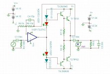
Well, you could add a couple of transistors and go Darlington. This circuit sims @ 0.018% distortion, 1kHz, putting almost 5 watts into 8 ohms. Clipping is at something over 800mV p-p input. I'm not 100% confident in the sim though. The bias depends on which LED you pick, since they can have different forward voltages depending on the color and type. The ones here are about 1.47V each.
Attachments
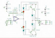
This one has pretty good performance. Don't worry about the specific parts, since I don't have time to find matching pairs of transistors. It outputs over 6 volts into 8 ohms/20nF with low distortion at 1kHz and 800mV p-p input. Distortion @ 20kHz is about 0.1% for the same input. Bandwidth is really good and rolls off nice and smooth. This is all in simulation of course.
Attachments
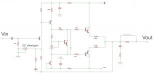
Regarding the circuit in post 14, J-fets really are wonderful and any audio designer who's anybody has a special place for them. The output devices could be any Darlington pair, TIP120/TIP125 are TO-220, I would limit Vcc to +/-20V @ 8R, or maybe 2N3038/2N3035 are TO-126, I would limit Vcc to +/-10V @ 8R. Because the output devices are Darlington, the Vbe multiplier that bias the thermal stability should be as well since temperature co-efficient is related to beta, or in the case of Darlington devices, (beta T1) X (beta T2). In the circuit, I forgot a 1 to 10uf cap should be placed across the Vbe multiplier from collector to emitter, this helps tie the AC path for the bases of the two output devices together. Also a fixed resistor could be added in series with the Vbe multiplier pot for less mA of output bias per turn.(I like to use 10 or 20 turn pots for Vbe multiplier.) The output stage can be re-configured to use single transitors but it would require the addition of a driver stage.
The bottom J-fet is a constant current source. A J-fet with the gate and source tied together will produce a constant current source at about what Idss is on the datasheet for that particular J-fet. This is the VAS load, it places a constant impedance on the VAS. Simple, eh? Because the output devices are Darlington, the current gain is very high so the VAS can be a TO-92 small signal device, like 2N3906 or BC560, bias at 3 or 5mA. So choose a J-fet that Idss is in that range, J201 is a common device that is close. Idss is easy to measure. The resistor from base to emitter of the VAS transitor sets the current for the input J-fet, and so the other resistors will need to be figured from this. If you use a J201 for the input stage as well I would go for about 0.5 - 1mA. (Vbe+VRe)/R=I.
The input transistor is a J-fet but it is bias not at Idss but in the saturation region. Since Vgs for a N-ch J-fet is negative, there is 0VDC on the gate of the input J-fet, but the source will bias slightly positive. The "differential" part of this amplifer is so that +Vin is the gate, and -Vin is the source. Feedback returns in the same way as in the op-amp, the output feeds back to -Vin. Again you can put a fixed resistor in series with the gain/offset pot to make it less sensitive. The voltage gain is set by the divider, the feedback resistor and pot. Adjusting the DC offset also sets the gain, there will be a setting where DC out is 0VDC. You can elaborate and use a fixed resistor ratio here and use an op-amp as a DC servo as well. The compensation paralell the feedback resistor helps set the phase margin so the power amp will not become a power oscillator. You can experiment with taking this from the output of the VAS as well.
I have not simulated or built this circuit but I bet it will do better than 0.06% distortion @1KHz.
The output devices could be any Darlington pair, TIP120/TIP125 are TO-220, I would limit Vcc to +/-20V @ 8R, or maybe 2N3038/2N3035 are TO-126, I would limit Vcc to +/-10V @ 8R. Because the output devices are Darlington, the Vbe multiplier that bias the thermal stability should be as well since temperature co-efficient is related to beta, or in the case of Darlington devices, (beta T1) X (beta T2). In the circuit, I forgot a 1 to 10uf cap should be placed across the Vbe multiplier from collector to emitter, this helps tie the AC path for the bases of the two output devices together. Also a fixed resistor could be added in series with the Vbe multiplier pot for less mA of output bias per turn.(I like to use 10 or 20 turn pots for Vbe multiplier.) The output stage can be re-configured to use single transitors but it would require the addition of a driver stage.The bottom J-fet is a constant current source. A J-fet with the gate and source tied together will produce a constant current source at about what Idss is on the datasheet for that particular J-fet. This is the VAS load, it places a constant impedance on the VAS. Simple, eh? Because the output devices are Darlington, the current gain is very high so the VAS can be a TO-92 small signal device, like 2N3906 or BC560, bias at 3 or 5mA. So choose a J-fet that Idss is in that range, J201 is a common device that is close. Idss is easy to measure. The resistor from base to emitter of the VAS transitor sets the current for the input J-fet, and so the other resistors will need to be figured from this. If you use a J201 for the input stage as well I would go for about 0.5 - 1mA. (Vbe+VRe)/R=I.
The input transistor is a J-fet but it is bias not at Idss but in the saturation region. Since Vgs for a N-ch J-fet is negative, there is 0VDC on the gate of the input J-fet, but the source will bias slightly positive. The "differential" part of this amplifer is so that +Vin is the gate, and -Vin is the source. Feedback returns in the same way as in the op-amp, the output feeds back to -Vin. Again you can put a fixed resistor in series with the gain/offset pot to make it less sensitive. The voltage gain is set by the divider, the feedback resistor and pot. Adjusting the DC offset also sets the gain, there will be a setting where DC out is 0VDC. You can elaborate and use a fixed resistor ratio here and use an op-amp as a DC servo as well. The compensation paralell the feedback resistor helps set the phase margin so the power amp will not become a power oscillator.
You can experiment with taking this from the output of the VAS as well.I have not simulated or built this circuit but I bet it will do better than 0.06% distortion @1KHz.
Last edited:
Regarding the circuit in post 14, J-fets really are wonderful and any audio designer who's anybody has a special place for them.
The bottom J-fet is a constant current source. A J-fet with the gate and source tied together will produce a constant current source at about what Idss is on the datasheet for that particular J-fet. This is the VAS load, it places a constant impedance on the VAS. Simple, eh? Because the output devices are Darlington, the current gain is very high so the VAS can be a TO-92 small signal device, like 2N3906 or BC560, bias at 3 or 5mA. So choose a J-fet that Idss is in that range, J201 is a common device that is close. Idss is easy to measure. The resistor from base to emitter of the VAS transitor sets the current for the input J-fet, and so the other resistors will need to be figured from this. If you use a J201 for the input stage as well I would go for about 0.5 - 1mA. (Vbe+VRe)/R=I.
The input transistor is a J-fet but it is bias not at Idss but in the saturation region. Since Vgs for a N-ch J-fet is negative, there is 0VDC on the gate of the input J-fet, but the source will bias slightly positive. The "differential" part of this amplifer is so that +Vin is the gate, and -Vin is the source. Feedback returns in the same way as in the op-amp, the output feeds back to -Vin. Again you can put a fixed resistor in series with the gain/offset pot to make it less sensitive. The voltage gain is set by the divider, the feedback resistor and pot. Adjusting the DC offset also sets the gain, there will be a setting where DC out is 0VDC. You can elaborate and use a fixed resistor ratio here and use an op-amp as a DC servo as well. The compensation paralell the feedback resistor helps set the phase margin so the power amp will not become a power oscillator.
I have not simulated or built this circuit but I bet it will do better than 0.06% distortion @1KHz.
I'm more than willing to simulate your circuit, but I need all of the component values first.
You don't seem to realize that this circuit is driving 8 ohms plus 20nF at full power. It may only produce 5 watts or so, but I'm keeping it as close to his original circuit as I can. That's why I used that particular op amp and those particular output transistors. He wants something simple and to him this is what simple looks like. Simple doesn't usually perform as well as something more sophisticated, which is why they are that way in the first place. Someone realized that if they added this part or this wire, then the circuit would perform better, but it also made the circuit more complex. The OP wants it simple and I'm trying to keep it that way.
If he wanted complex, he could try to duplicate a Krell KSA 100 or something like that.
Regards!
First of all i'm thankful for all attention for this topic.
So. Yeah, i really want a super simple amplifier wich can supply my need: a amp for my pc.
Not just that, i'm here to learn more how to build amplifiers, and, as you guys can see, i'm using a OPAMP as a preamp because i don't figure out, yet, how to build one specifically for my needs with some transistors or JFETS or whatever.
Any suggestions are welcome, keep that way.
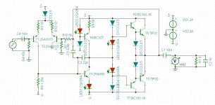
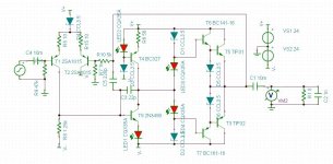
OK, this one produces a hair over 9 watts into 8 ohms/20nF @ 1kHz, 1.1V p-p input with 0.007% distortion at that point just before clipping. The diodes are 3.5mA CRD's from Central Semi. Bandwidth is good. Distortion @ 20kHz near clipping (9 watts output) is 0.1%.
I think the opamp is the big limitation here. There needs to be a VAS between the opamp and the output stage in order to produce more power. I hesitate to add one because he wanted to keep it as simple as possible. Also, I kind of doubt this circuit is ever going into class B operation. I think it pretty much stays in class A, though I don't know how to check that.
I do know that in my Crown D75 amps, there's a VAS and a Vbe multiplier, at least, between the opamp input stage and the output transistors.
Attachments
This is something I've received a ton of help on in another thread. Thanks to this thread I've got a little bit more for it now. Clipping level for this one is 15 watts into 8 ohms/1nF @ 1kHz. I define clipping as the 0.5% distortion point.
Attachments
Regards!
First of all i'm thankful for all attention for this topic.
So. Yeah, i really want a super simple amplifier wich can supply my need: a amp for my pc.
Not just that, i'm here to learn more how to build amplifiers, and, as you guys can see, i'm using a OPAMP as a preamp because i don't figure out, yet, how to build one specifically for my needs with some transistors or JFETS or whatever.
Any suggestions are welcome, keep that way.
Oh, the absolute most simple way to make an amp for your PC is to use a chip amp, in particular a Gain Clone. It's just one chip, some resistors and capacitors, and a power supply. I made one and it works great.
LM3886 - High-Performance 68W Audio Power Amplifier with Mute
There is a whole forum here devoted to chip amps.
Shure... but i'm exagerating about SUPER simple. The DIY loses a little bit of sense for me when chip amps are used. They're done, no need for modifications, just hardware job on it.
I'm looking here for knowledgement as well. But thanks for your attention! would help in another case...
I'm more than willing to simulate your circuit, but I need all of the component values first.
You don't seem to realize that this circuit is driving 8 ohms plus 20nF at full power. It may only produce 5 watts or so, but I'm keeping it as close to his original circuit as I can. That's why I used that particular op amp and those particular output transistors. He wants something simple and to him this is what simple looks like. Simple doesn't usually perform as well as something more sophisticated, which is why they are that way in the first place. Someone realized that if they added this part or this wire, then the circuit would perform better, but it also made the circuit more complex. The OP wants it simple and I'm trying to keep it that way.
If he wanted complex, he could try to duplicate a Krell KSA 100 or something like that.
Krell KSA 100 is much more complex than what I posted, double differential IPS compared to single transistor.
In fact the circuit you attached in post 50 looks more complex to me. As I stated before the resistor values very much depend on which J-fets you choose to use. Don't be afraid of J-fets, they really are wonderful devices and when you start using them you won't stop. A little simple math to figure the resistor values. 20Vp @ 8R is 25Wrms, suitable for a pair of TO-220 devices. 10Vp @ 8R is 6.2Wrms, suitable for a pair of TO-126 devices. If simulation is all that is concerning here, then the simplest circuit on paper is what I would go with. However, the circuit I posted can easily be constructed on breadboard for real world testing. The circuit has options. An RF transmitter may not be a terribly complex circuit on paper but to physically construct it can be more problematic. For example, none of the op-amp circuits in this thread include de-coupling caps at the Vcc or Vee terminals of the op-amp. Simulation may not reveal instabilities possibly due to poor construction. If simple is really all that is needed, well there is always the option of using an op-amp to drive a LM386 power amplifier. 2 IC's, it doesn't get simpler than that.Attachments
Another idea is to build an all discrete simple 5 transistor amp based on the Lin circuit.
It's AC coupled (which means safe for speakers) and runs on a single supply rail. It's also far more stable and forgiving of poor wiring layout and ground returns too.
For subjective sound quality I think it would beat any of the opamp + class B add on type designs.
The basic configuration is like this but would be altered to suit your PSU and components you can get.
Oral History Lin Page7 RCA GermaniumTransistors Audio
Well, SiliconRay is still giving away free PCB's for the 2005 JLH class A amplifier:
FREE JLH 2005 Class A Amplifier PCB - Boards | Kits | Components | Modules | Tools
It doesn't get much easier than that.
FREE JLH 2005 Class A Amplifier PCB - Boards | Kits | Components | Modules | Tools
It doesn't get much easier than that.
This is something I've received a ton of help on in another thread. Thanks to this thread I've got a little bit more for it now. Clipping level for this one is 15 watts into 8 ohms/1nF @ 1kHz. I define clipping as the 0.5% distortion point.
Could you explain me the roll of T4 and T9? and how this differential pair works? Also, why zener diodes dirctly polarized for current source? Thanks.
Could you explain me the roll of T4 and T9? and how this differential pair works? Also, why zener diodes dirctly polarized for current source? Thanks.
Oh, don't worry about that circuit. Those aren't zener diodes, but CRD's instead. Stick to something that is known and tested and you'll be fine.
- Status
- This old topic is closed. If you want to reopen this topic, contact a moderator using the "Report Post" button.
- Home
- Amplifiers
- Solid State
- My First Super Simple Class AB Amplifier