Hello everyone, so I have been repairing an old Rotel RA-812 amplifier. Replaced the driver transistors on one channel with BD140 and BD139 transistors, and replaced the 2SD427 outputs on the same channel with MJ21194's. Powered the amp up and it went fine for a short while, then the problems started.
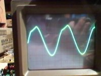
The amp ran fine for about 15-20 seconds, then the left channel which is the one I repaired suddenly went very quiet and distorted. After inspecting the amplifier I discovered that in my haste I forgot to solder the base and emitter pins on one of the output transistors. After I soldered them up, the amp ran fine and both channels sounded the same, but when testing with a sine wave the left channel would distort badly when the output voltage exceeded 4.5 volts or so. I took a photo of the oscilloscope to show what the waveform looks like, if I disconnect the speaker/load then the sine wave shows no distortion.
Its as if the amp only runs in class a mode then in class ab it distorts. I replaced all the electrolytic caps, and also removed and tested each individual transistor using the diode test feature on my multimeter and all of the transistors behaved as expected. Is this not a very thorough way to test if a transistor is good or bad?
Also and more importantly, what could cause such a waveform? Would it be worth replacing all of the original transistors and test each of the resistors?
I had set the bias to the correct level as per the service manual.
The amp sounds fine with music and can be turned up, but the distortion can still be heard on transients etc. Any help with this would be appreciated.
Attachments
Are the DC conditions correct... no DC offset ?
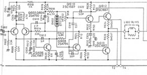
Check that the 0.47 ohms emitter resistors haven't gone high. Also check the other low vaue resistor. Drawings a bit blurry. The 3.3 ohm, the two 150 ohms and the 10 ohm.
I would turn the DC bias down (or use a bulb tester) while working on this just to be safe from blowing outputs.
Check that the 0.47 ohms emitter resistors haven't gone high. Also check the other low vaue resistor. Drawings a bit blurry. The 3.3 ohm, the two 150 ohms and the 10 ohm.
I would turn the DC bias down (or use a bulb tester) while working on this just to be safe from blowing outputs.
Thanks for the reply. I removed and tested the two emitter resistors and they were both fine.
Would running the amp without one of the power transistors connected possibly have damaged anything? It sounded fine but then went very quiet and distorted. It worked fine again after I had realised what I done and fixed it, apart from the mentioned problem.
Is it possible for a transistor to be faulty and yet pass the base to emmitter or collector diode test?
Are all the other resistors OK ?
The diode test isn't always conclusive. A transistor can be damaged and have low gain or can be leaky across a junction such that it doesn't register on the DVM. Usually careful DC checks will reveal the problem.
Where does that line of the collector of Q610 (NPN driver) go ? Is there full supply present there (when driven) ?
With the outputs unsoldered the amp will actually work but with limited drive. All the output current is delivered via the drivers and appropriate resistors depending which output was unsoldered.
DC checks are the way to find this. That means running with no load and carefully increasing the bias to bring the ouput stage into conduction. Hopefully that will reveal a problem.
It's a simple quasi complementary design, if the resistors are OK it has to be one of the semiconductors thats failed.
- Status
- This old topic is closed. If you want to reopen this topic, contact a moderator using the "Report Post" button.