Hoping someone can help out with my first LTSpice simulation. As a total newbie to Spice I have been following Bob Cordells excellent book for guidance but need some extra help.
The circuit is my own lateral FET amp and I have managed to get it to simulate OK apart I think from the FFT distortion runs.
Attached is the file for the amp if anyone is interested. I think all that's needed is in the zipped file.
My only guide has been following Bobs methods outlined in the book and using his complete model for a generic amp to see how the simulation
is set up and what to expect. When I run the sim I get an error message of sorts. I wondered if the long time constants in the amp could have any bearing on this ?
And as as I say, I am a total Spice newbie (it's taken me nearly 4 days to figure out how to get the 3rd party models into the thing") ) so please don't assume any knowledge whatsoever on my part for this.
) so please don't assume any knowledge whatsoever on my part for this.
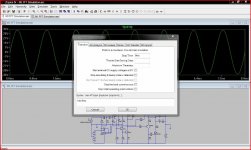
Attached is what I see when running the sim and how I have it set up.
The circuit is my own lateral FET amp and I have managed to get it to simulate OK apart I think from the FFT distortion runs.
Attached is the file for the amp if anyone is interested. I think all that's needed is in the zipped file.
My only guide has been following Bobs methods outlined in the book and using his complete model for a generic amp to see how the simulation
is set up and what to expect. When I run the sim I get an error message of sorts. I wondered if the long time constants in the amp could have any bearing on this ?
And as as I say, I am a total Spice newbie (it's taken me nearly 4 days to figure out how to get the 3rd party models into the thing
) so please don't assume any knowledge whatsoever on my part for this.Attached is what I see when running the sim and how I have it set up.
Attachments
-
M1 1Khz Distortion.zip6.3 KB · Views: 46
-
 FFT Results (1024x617).jpg221.5 KB · Views: 92
 -
 Settings 2 (1024x615).jpg260.5 KB · Views: 153
 -
 Settings 1 (1024x614).jpg240.8 KB · Views: 172
 -
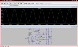 Simulation Run (1024x615).jpg232.8 KB · Views: 175
 -
 Error 2 (1024x616).jpg232.1 KB · Views: 178
 -
 Error 1 (1024x613).jpg243.4 KB · Views: 192
Member
Joined 2009
Paid Member
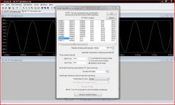
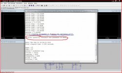
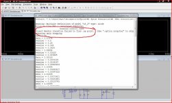
Well the 2nd error tells you that it can't do a Fourier analysis on V(out) because there isn't a node in the circuit that is labelled 'V(out)' for it to work with. Just add a label - it's a rectangular box with 'A' in it on the menu bar and it says 'label net' when you run your mouse over it. Attach a label to the output of the amp and name it "out".
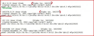
The 1st error looks like you have two models loaded up for the same diode. Maybe you can check to see if you have the same diode model in two or more of the '3rd party' models you have loaded in.
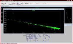
for your FFT - run it longer to move the 'noise floor' or whatever you call it down and expose those spikes - it's usually capacitors that require charging up that cause this phenomena and some people replace the with batteries for much faster simulations (look up keantokens guide on spice somewhere on this forum). Also, including more signal oscillations into the analysis will narrow up the peaks too.
An example of how I do things (for good or bad) is somewhere in my TGM5 thread.
The 1st error looks like you have two models loaded up for the same diode. Maybe you can check to see if you have the same diode model in two or more of the '3rd party' models you have loaded in.
for your FFT - run it longer to move the 'noise floor' or whatever you call it down and expose those spikes - it's usually capacitors that require charging up that cause this phenomena and some people replace the with batteries for much faster simulations (look up keantokens guide on spice somewhere on this forum). Also, including more signal oscillations into the analysis will narrow up the peaks too.
An example of how I do things (for good or bad) is somewhere in my TGM5 thread.
Last edited:
I often run several hundred miliseconds at 10ns max timestep to get clear FFTs. However, if you're looking to save time 50 milliseconds at that period lets the first few harmonics stick up high enough to get a rough idea what it will look like. For instance, it looks like you're dealing with about -60dB second harmonics at +30dB output. This can be seen even with your really short sim. That probably wont change much, only become clearer with increased number of data points.
Thanks for the pointers on this.
Bigun... the multiple definitions error. I have no idea on that as I only have the .txt Cordell models included with the file. I haven't added anything to the libraries. The circuit has no diodes as such either... I'll work on that one later. Having said that Bobs worked examples which I have downloaded from his site also include "the same" .txt file and I think there may be differences between them.
I can remove the servo and add a DC bias in series with the input signal. That leaves the 470uf feedback cap. I suppose I could return the feedback to a voltage source to... I'll have a play.
Added a Vout node (thanks).
djoffe and Andrew.
The servo does put a large peak in the LF AC response. I'll try removing the servo and time constants as mentioned.
Andrew... setting and getting a feel for the simulation settings is quite a challenge (for me) although it's all starting to make a bit more sense..
I did a simulation on the amp with no signal and a large triangular ripple component on the rails which was interesting.
Hi Mooly, I was simulating a standard B1 circuit last night. It only has 1 X 1uf cap and 1 X 10uf cap in it and I needed to run it for 20 seconds to get it to stabilize.
The thing to look for is the DC Component figure just above your FFT results. If there aren't enough zeros after the decimal you will get a sloping FFT, and you will need to up the simulation time. I think the minimum I can get away with with most of the sims I've done is about 320ms which can be time consuming. I'll have to look at keantokens battery tip as that will save me a lot of computation time!
Tony.
Last edited:
Mooly, I mentioned using 10ns max timestep. You don't need that fine of a period for a 1kHz sim, you need more drive signal cycles. I forgot to mention that I simulate llinear amps (usually very low distortion) a lot at 10kHz instead of 1k to get a better idea. .1uS is fine for 1k sims. (although sometimes it still leaves some spikes in the hundreds of kHz that aren't real.)
You got the idea with removing anything with a big settling time. It's better to do that than just running for days into the bit bucket with circuit sections added that may not simulate accurately at audio frequencies anyway, unless you have oddly accurate cap models n stuff.
You got the idea with removing anything with a big settling time. It's better to do that than just running for days into the bit bucket with circuit sections added that may not simulate accurately at audio frequencies anyway, unless you have oddly accurate cap models n stuff.
Thanks Tony, I'd wondered about the sloping FFT results (as in post #1 for example).
Andrew, I see what you mean !
It seems less is better when it comes to simulations like this. Before I removed the time constants I tried doing a longer sim but had to halt it as it was taking forever.
I can see I've a lot to learn on all this...
Andrew, I see what you mean !
It seems less is better when it comes to simulations like this. Before I removed the time constants I tried doing a longer sim but had to halt it as it was taking forever.
I can see I've a lot to learn on all this...
Hi,
I´m frequently using these commands:
.param freq=1kHz *allows to parametrize the frequency. Calculation time for Transient simulation is automatically adjusted, e.g 200ms for 1kHz and 20ms for 10kHz*
.param period=1/freq ncycles=2
.tran 0 {100*ncycles*period} 0 {pi/3.14*period/2e3}
.four {freq} V(out)
*the input voltage needs {freq} as frequency value, e.g. SINE(0 1 {freq})*
.options plotwinsize=0
and also using these:
;ac oct 100 100m 10Meg
;noise V(out) V1 oct 100 20 20k * Node needs to be labeled ´out´, V1 is input voltage*
;tf V(out) V1 * Node needs to be labeled ´out´, V1 is input voltage*
.options plotwinsize=0
;op
jauu
Calvin
Thanks Calvin. I'm going to have to have a major play on all this. It's only by trying all this and making my own mistakes... and asking on here that I will slowly begin to master this.
----------------------------------------------------------------------------------------------------------------------
Managed to fix the "multiple definitions error".
----------------------------------------------------------------------------------------------------------------------
Managed to fix the "multiple definitions error".
Attachments
- Status
- This old topic is closed. If you want to reopen this topic, contact a moderator using the "Report Post" button.
- Home
- Amplifiers
- Solid State
- Help needed in running LTSPice FFT simulation on the M1 Lateral FET amp