Hi,
can anyone explain to me why Anthony has put Q13 (IRF610 - Voltage amplification transistor) on the main heatsink?
Is it to help Q12 prevent thermal runaway when the sink is heating up, or is it just to keep it cool? According to my simulations approx. 1W gets dissipated in Q13, which should not be a problem to cool down without having to put it on the main heatsink.
The problem is that my PCB does not allow mounting Q13 directly onto the main heatsink, therefore i'm thinking of adding a small sink for the driver.
Comments on adding a separate heatsink for the voltage amplification transistor Q13 is very much appreciated.
Here is the schematic for the n-channel amp:
http://www.aussieamplifiers.com/downloads/n-channel amp.pdf
Regards
Pelle
Banned
Joined 2002
Banned
Joined 2002
Banned
Joined 2002
JasonL,
it looks like you have only placed the Q13 on the heatsink. If you have had problems with your amp blowing up or running hot then it's because you have not placed Q12 (where it says MJE340 on your pcb) ontop of one of the output-mosfets.
edit:
JasonL, I see that you have written Q13 beside the transistor that is Q12 in Anthony's new schematic. The designations may differ between his old and his new schematic.
But I still think you should move Your Q13 to the heatsink also.
-Pelle
Banned
Joined 2002
JasonL,
try adding the Q12 to the top of one of the mosfet's, best on top of the mosfet that draws the most current.
But leave Q13 on the main heatsink since it needs to be cooled down.
Post your comments here after you've tried it.
-Pelle
Edit:
I still need to know if it's totally OK to mount Q13 on an external heatsink.
Banned
Joined 2002
Pelle well i did what you said and well heh my amplifier no longer works now. Not blaming you just want to solve the problem .
i powered it up no smoke no bangs or any thing not even any heat. Cool but when iwent to put a speaker up to it. POP the speaker almost blew.. so i used my dmm and found out that there is a raw 74.5vdc ( te rail voltage. ) on the out put.. Any clue to why this is happening. : O) ..? Good thing i didn't sell it id feel bad to the person that took it home.
i powered it up no smoke no bangs or any thing not even any heat. Cool but when iwent to put a speaker up to it. POP the speaker almost blew.. so i used my dmm and found out that there is a raw 74.5vdc ( te rail voltage. ) on the out put.. Any clue to why this is happening. : O) ..? Good thing i didn't sell it id feel bad to the person that took it home.
Jason,
1) are you ABSOLUTELY sure that the transistor you mounted on the heatsink is isolated from the heatsink?
2) since you probably use wires now to connect the transistor: nothing that touches some other metal?
3) are you sure you attached the wires the right way? mayby rotated 180 degrees?
Grtz, Joris
P.S. Are you sure your speaker is still working? Not so many speakers that can handle 74.5 Vdc!
Banned
Joined 2002
yeah i checked the speaker it is still alive, and running well. But i just cant figure out why it is pumping the rail voltage through the speaker. i looked at it with my dmm and it is a - voltage not a positive. i looked at the pads no ware marks no metal shavings under or near the fets either. and yes i had the polarity properly.
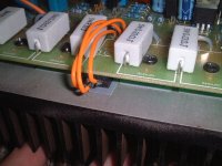
Is the picture correct.
I might be making a mistake but I think the transistor is connected wrong. If you look at the transisor in the picture from the ceramic resistor end , base is on the left.
The transistor has physically the same orientation when mounted under the board on the heat sink. So left terminal goes to base on board etc. But it "look" like the leads have been reversed except for the middle one!
Am I wrong ?
Cheers,
Ashok.
Banned
Joined 2002
Well in them previous pictures the amplifier ran perfectly and strong. O ) but now it just outputs voltage into the speaker output. BUT. when it was in storage it might have gotten bumped or something. i checked all the solder joints and they all seemed find. i guess i should have powered it up before i did this

Humm no idea what to start with now either.
Humm no idea what to start with now either.
Banned
Joined 2002
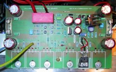
here is the board before it worked. : O ) and it is the same way still BUT not working : O )
http://24.71.244.254/Photo/view_photo.php?set_albumName=album15&id=DSCF0029
http://24.71.244.254/Photo/view_photo.php?set_albumName=album15&id=DSCF0029
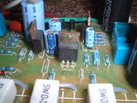
I got it wrong.
Yes this picture shows it clearly. I got the orientation wrong from the close up picture. Any possibility of the insulation between the transistor and heat sink being faulty ?
Cheers.
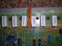
Something wrong here. In the picture in your earlier post the transistor seems to be facing the wirewounds and the edge of the board. In the current picture the transistor is facing into the board. If both are identical , I must be really getting mixed up.
Yes this picture shows it clearly. I got the orientation wrong from the close up picture. Any possibility of the insulation between the transistor and heat sink being faulty ?
Cheers.
Something wrong here. In the picture in your earlier post the transistor seems to be facing the wirewounds and the edge of the board. In the current picture the transistor is facing into the board. If both are identical , I must be really getting mixed up.
- Status
- This old topic is closed. If you want to reopen this topic, contact a moderator using the "Report Post" button.
- Home
- Amplifiers
- Solid State
- Q13 in Holton's n-channel amp