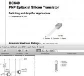
You can use BC640 but bear in mind the pinout will be different so you will have to bend the leads to fit.
Sure?
Attachments
GoranB, there is a relay based circuit according to the schematic, but it is not a conventional DC protection. It appears to be simply for anti-thump and thermal overheat protection. It connects the current source made by Q607 to the VAS buffers Q609/Q611. If the relay or its control circuitry fails to energise, there will be no sound.
You are right, i just didnt noticed it. Thanks.
Sure?
No
") I forgot that the BC639/640 are the same die as a BD139/140 and thus follow the TO-126 pinout
I forgot that the BC639/640 are the same die as a BD139/140 and thus follow the TO-126 pinout..... here is a few facts
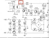
--according to the schematic rail voltage should be around 41+41 volts ( i presume that you understand what this means and also the proper way to measure that is measuring at the collector of Q627 and ground expecting around +40 volts and collector of Q631 and ground expecting - 40 volts
---lower voltage than expected 40+ volts will mean faulty transformer faulty capacitors short circuit somewhere in the chain of supply or output and or faulty rectifier ...bear in mind that you may as well have a faulty multimeter .
---Next important thing will be to make sure that you relay clicks the specific relay will probably work as an anti-thumb relay on start up and as a thermal protection of the amplifier ... Correct said relay, driver transistor, diodes,zeners, and peripherals should work ...if not he relay will not click ( keep in mind that this relay will not offer any DC protection and make sure that all your testings take place with no speakers connected to your amplifier )
---It is not repair procedure to start replacing transistors ( especially if not original ) to trace the problem
---Install if possible safety measures That will be a bulb of 100w in series with mains to work as a power limiter and then you may bypass the relay in order to troubleshoot the rest of the circuit
---First area though to verify is why measuring voltage in your amp is not according to the schematic
kind regards
sakis
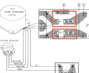
The low voltage not having 41 volts made me take off the fuses right after the transformer (F901/902), see attached pic...
The voltage which I measure there is 2x26,4 volts AC. If that means the transformer is faulty I have to give up. Exchanging the transformer would be to expensive for me.
The voltage which I measure there is 2x26,4 volts AC. If that means the transformer is faulty I have to give up. Exchanging the transformer would be to expensive for me.
Attachments
Last edited:
This amp has 220 and 240V main selector.
In Europe the main had been changed from 220V in continental Europe
and 240V in the UK to 230V for norms unification purposes.
If your amp is on the 240V position , the supply voltage will be about 5% lower,
that is 2V , than the value in the schematic wich itself is given with a 5%
precision by the manufacturer.
Power output will be about 10% lower than the one measured with
the correct supply voltage.
Switching to the 220V position would increase the supply voltage
in respect of the schematic value by 5% and increase output power by 10%.
All in all , and considering the usual variations , your amplifier supply voltage
seems normal and you shouldnt bother about it.
It s best to stick to the 240V position, though , despite the slightly
lower output power.
The slightly low voltage will not be significant in this case. All it will mean is a little less output power. It could be that your mains voltage is slightly low, which would cause the secondary voltages to be low also. For 41V supplies you would need 29VAC on the secondaries.
You say thet you have 3mV on the speakears terminals but if the relay is not closing that is irelevant.
Try to measure from the relay terminals to ground and post the results
Any DC on the relay pins will enable the speaker protection.
Good luck
I am measuring 37 volts on the coil of the relays. I should measure 24 volts instaed
Last edited:
This amp has 220 and 240V main selector.
In Europe the main had been changed from 220V in continental Europe
and 240V in the UK to 230V for norms unification purposes.
If your amp is on the 240V position , the supply voltage will be about 5% lower,
that is 2V , than the value in the schematic wich itself is given with a 5%
precision by the manufacturer.
Power output will be about 10% lower than the one measured with
the correct supply voltage.
Switching to the 220V position would increase the supply voltage
in respect of the schematic value by 5% and increase output power by 10%.
All in all , and considering the usual variations , your amplifier supply voltage
seems normal and you shouldnt bother about it.
It s best to stick to the 240V position, though , despite the slightly
lower output power.
Despite the fact of a voltage selector on the schematic, the amp has none!
My voltage is 223 volts AC...
Above said very correct and a few volts will not effect much of performance .... expect as said a bit of lower power less from the max
37+37 volts are more than enough to operate the amp
proceed with the rest
One more think you can do is use an bulb to load the transformer at AC conditions to verify that after all the transformer doesn't have an actual problem .
there is a very small possibility that the measure you read is inductive and not real ..... very very unlikely still a small possibility though ....
The slightly low voltage will not be significant in this case. All it will mean is a little less output power. It could be that your mains voltage is slightly low, which would cause the secondary voltages to be low also. For 41V supplies you would need 29VAC on the secondaries.
Yes, but when I started measuring voltages on transistors yesterday, some were really 4 volts lower then the the ones on the schematic. So, should I exchange Q638/639 now? I could get BC 640 for them easily...
I am measuring 37 volts on the coil of the relays. I should measure 24 volts instaed
that is correct cause you measure the relay pin in reference to ground at the specific circuit 24 volt will be present only between the relay pins and not in reference to ground
As i said this is secondary ...you may as well, jumper the relay but only to test if the rest of your amp functions and only if safety measures have been taken
I dont understand, as on the schematic is written 24 volt on the coil...that is correct cause you measure the relay pin in reference to ground at the specific circuit 24 volt will be present only between the relay pins and not in reference to ground
As i said this is secondary ...you may as well, jumper the relay but only to test if the rest of your amp functions and only if safety measures have been taken
Attachments
yes but in reference to the relay pin not reference to ground
and one way or another please take your brain and eyes from this .... for testing procedures only the relay can be bypassed .....
( the related circuit will actually "regulate" the ground to 24 volt not the + so that is why you will always measure rail voltage there = 37 volts )
and one way or another please take your brain and eyes from this .... for testing procedures only the relay can be bypassed .....
( the related circuit will actually "regulate" the ground to 24 volt not the + so that is why you will always measure rail voltage there = 37 volts )
Check R698. There is no regulation of the voltage for driving the relay, so it is down to R698 + the resistance of the coil to set the voltage.
R698 is ok.
- Status
- This old topic is closed. If you want to reopen this topic, contact a moderator using the "Report Post" button.
- Home
- Amplifiers
- Solid State
- ROTEL RA-820BX3 not working