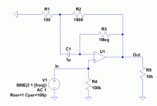
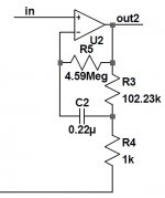
Are there any flaws with the feedback capacitor arrangement shown in the attachments? It seems to allow a much smaller value capacitor to be used than a capacitor in series with R1, which is what I have seen used commonly. It sims OK in LTspice with the ideal opamp but, since it's so simple yet I haven't seen it used, I want to check.
Attachments
I can't see anything wrong with it. You separated out the DC and AC feedback, which allows you a much higher R for the DC feedback hence a lower C value. Creative circuit.
There are two issues I think you should verify:
* In practise, there is a limit to how high you can make the DC feedback R before you get in trouble with output offset due to bias currents. I expect your 1 Meg to be too high in most cases, so it will be less advantageous as it looks in your diagram;
* The source is now DC coupled to the output. Depending on resistance values and source DC offset, a DC current will flow through the source. Don't know what the effect of that on the source will be.
jan didden
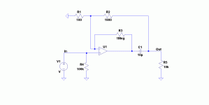
If I'm not mistaken, C1 would have to carry very little signal current here, which I'd see as a definite advantage for crummy nonlinear caps in particular. However, you still want to have C1's impedance to be reasonably small vs. R1||R2 in the relevant frequency ranges in order to keep noise down.
I could definitely see this variant being of use under certain circumstances (not like it would be all new or anything, definitely seen it in old power amp IC datasheets). When using film caps and low gains, I'd prefer the "standard" one though.
I could definitely see this variant being of use under certain circumstances (not like it would be all new or anything, definitely seen it in old power amp IC datasheets). When using film caps and low gains, I'd prefer the "standard" one though.
You have placed a capacitor between the feedback resistor junction and the inv input of the opamp. Any noise picked up by the cap will be amplified by the full loop gain if the opamp. The capacitor is physically large and acts as an antenna compared to just putting the junction of the feedback resistors as close as possible to the inv input which is a must with opamps or any feedback amplifiers. My honest opinion: this is not a step forward and for the reasons cited, is why you do not see this approach used in general.
The + input also wants to see 1M to GND at DC, else suffer an offset.
If you have to use an input cap to do that, perhaps conspire to have
this extra "antenna?" on the + input buck the - pickup problem...
Same orientation etc. etc...
Not sure I actually believe that, but assuming it was true...
If you have to use an input cap to do that, perhaps conspire to have
this extra "antenna?" on the + input buck the - pickup problem...
Same orientation etc. etc...
Not sure I actually believe that, but assuming it was true...
Last edited:
I thought for a minute you were being serious there . . . ;-)
Its amazing how high end audio companies will wrap absolute marketing b.s. around something that is totally sub optimal and then market it as the best thing since sliced bread, to then be taken up by the high end community as gospel. As bad as all those make-up adverts . . .
. . . the latest being a print advert featuring Rachel Weitz which was banned by the Advertising Standards Authority in the UK for being too misleading - not Ms RW that is, but the makeup company's claims. It appears they were too heavy handed with the photoshopping, since RW is 41 years old they did not feel the photo represented reality.
Last edited:
Thanks everyone for the replies. I intended this scheme only for use with JFET-input amplifiers, so I don't think there would be issues with voltage offset even with 1M-ohm resistor - correct?
This is for the inverting case, but is that any different to the non-inverting case from my first post? The source DC current will be its offset divided by R4. This is a pretty common case I think.
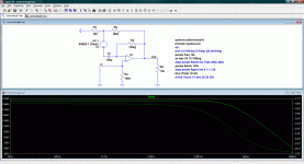
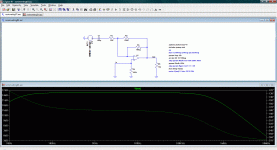
Is it amplified by the loop gain, or by the closed loop gain of (R1+R2)/R1? I had almost convinced myself of the latter qualitatively, then I ran the attached sims which I hope are OK to model what you're referring to. If so, no difference between the two cases.
The source is now DC coupled to the output. Depending on resistance values and source DC offset, a DC current will flow through the source. Don't know what the effect of that on the source will be.
This is for the inverting case, but is that any different to the non-inverting case from my first post? The source DC current will be its offset divided by R4. This is a pretty common case I think.
You have placed a capacitor between the feedback resistor junction and the inv input of the opamp. Any noise picked up by the cap will be amplified by the full loop gain if the opamp. The capacitor is physically large and acts as an antenna compared to just putting the junction of the feedback resistors as close as possible to the inv input which is a must with opamps or any feedback amplifiers. My honest opinion: this is not a step forward and for the reasons cited, is why you do not see this approach used in general.
Is it amplified by the loop gain, or by the closed loop gain of (R1+R2)/R1? I had almost convinced myself of the latter qualitatively, then I ran the attached sims which I hope are OK to model what you're referring to. If so, no difference between the two cases.
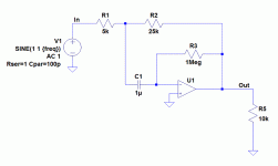
Attachments
You know what steveh49, you are correct. In the non inverting mode, the noise is amplified by the closed loop gain and not the loop gain. Easy to see why. The opamp simply adjusts the output so that Vinv=Vninv. So the noise at the opamp output must thus be the closed loop gain x the noise.
However , I would still not put the cap there. You are basing the op amp with a high value resistor (1M). This limits you to a fet input device, or some offset adjustment.
Any reason why you wanto AC couple te signal like this? Any event opamp will give you negligible offset, even with the 27dB you show. Easier in my view to simply couple te input signal through a cap and be done with it.
This is exactly the same circuit as shown in Linear Audio Vol 1 by Kendall Castor-Perry. He also makes the point that it can only be successfully be used with very low leakage inputs.
jan didden
I might have to look at getting this article...
Any reason why you wanto AC couple te signal like this? Any event opamp will give you negligible offset, even with the 27dB you show. Easier in my view to simply couple te input signal through a cap and be done with it.
I wasn't necessarily looking at chip opamps, I am also considering power amps. A lot of power amps include an electrolytic capacitor in series with R1 and I started by trying to include this capacitor in the feedback loop (sounds like that was what Kendall Castor-Perry did). It doesn't seem to work as intended though, as the distortion is amplified which is how I knew to question the amplification of the antenna pickup.
As Jan says, the idea now is simply to use a much smaller capacitor. Because it can be reduced by orders of magnitude, this can make the difference between electrolytic and plastic film (distortion). Now that you've raised antenna pickup, I assume that a 10uF electrolytic is better than a 470uF electrolytic in this regard, so there is that potential improvement also. Keen to hear your thoughts.
Self shows meaurements of distortion from Al electrolytic feedback caps at the gnd of the gain network - make it really big and there's little audio frequency Vdrop to distort
it really is a non-problem by measured distortion
and by being big and connected to gnd a big electro shunts interference to gnd up to frequencies where it becomes inductive
you should take other measures to avoid hi frequency high amplitude interferance any where near your amp feedback inputs anyway
the high impedance of the small cap and MegOhm feedback R at the op amp input node makes a very sensitive electrostatic antenna - likely more than making up for smaller "collecting" area
fet input op amps have very high ib tempco - get them even a little hot and they have noticable input current - certainly when magnified by 1 MegOhm
Last edited:
and by being big and connected to gnd a big electro shunts interference to gnd up to frequencies where it becomes inductive
Does this mean it is better to have the feedback capacitor connected between ground and R1, than between the feedback node and R1 (R1 connected to ground)?
the high impedance of the small cap and MegOhm feedback R at the op amp input node makes a very sensitive electrostatic antenna - likely more than making up for smaller "collecting" area
Does this apply equally if a small capacitor is used at the output as shown in the attachment? Is it better to use an oversized capacitor here also?
Attachments
Does this apply equally if a small capacitor is used at the output as shown in the attachment? Is it better to use an oversized capacitor here also?
Still interested in including output capacitors in the feedback loop, so bringing this back to the top of the pile.
- Status
- This old topic is closed. If you want to reopen this topic, contact a moderator using the "Report Post" button.
- Home
- Amplifiers
- Solid State
- Alternative feedback capacitor arrangement