Vintage SONY TA-F555ES DC BALANCE adjustment problem
Hello,
I just got a new amp. For me, this is the first amp from the upper class, though, oldish, and I'm very happy with that.
This is old amp, I would say it is from '83 year. It uses SONY's "Audio Current Transfer" technology. Inside it is in very good condition, with all original parts: Sanken 1216/2922 transistors, big, black For Audio ELNA caps 22000uf/63V, and simply all other parts are original, I would say.
Because the amp is older, I would like to check for BIAS and OFFSET adjustments, and adjust for proper values. Sony calls them DC BIAS and DC BALANCE adjustments.
This amp has DC BALANCE adjustments in 2 boards. The first is "EQ Section DC BALANCE" and the second is the "V-I Section DC BALANCE".
I tried to follow service manual's adjustment procedure, and managed to check and correct DC BIAS and EQ Section DC BALANCE. But I have problems checking and setting V-I Section DC BALANCE. Here is the procedure for adjusting V-I Section DC BALANCE from the manual:
Everything up to here is ok, but from now on, some problems come to the surface. First, on the amp, these two test points are marked as TP3 and TP4 (in manual TP5 and TP6). But that, by itself, would not be any problem. The real problem is, trying to follow the adjustment procedure, I don't manage to measure ANY voltage on TP3 and TP4. Always get 0V DC (or better say 0mV DC). To be clear, I measure between TP3 and chassis ground or TP4 and chassis, as indicated in the manual, on the pic above.
First, I was happy with the 0.0mV results for the V-I Section DC BALANCE, because, it should be 0 V, but, that was a little strange, because, DC BIAS and EQ BALANCE were greatly off (about 15-20%). So I tried to turn the trim pots RT201 and RT251 and to observe the reading change on the Vmeter - but the values remain 0mV. I turn a couple turns both pots, but still no change in reading on the VOM on the test points.
And that is it!
I have low knowledge about amp principles of operation, and I'm trying hard, but do not manage to understand the theory of the V-I Section DC BALANCE adjustment, first, and second, I would like to get some help for proper adjustment of the V-I BALLANCE for this amp, because, obviously, the service manual is not 100% written good, and not 100% appropriate for this amp, though, it is service manual for the exact model TA-F555ES.
I can try to provide you photos of my amp, or any part of it, just ask for them, please, and will try to find, and post, the service manual, so you can see for yourself the complete schematics, diagrams, adjustments, etc.
Thanks.
Hello,
I just got a new amp. For me, this is the first amp from the upper class, though, oldish, and I'm very happy with that.
This is old amp, I would say it is from '83 year. It uses SONY's "Audio Current Transfer" technology. Inside it is in very good condition, with all original parts: Sanken 1216/2922 transistors, big, black For Audio ELNA caps 22000uf/63V, and simply all other parts are original, I would say.
Because the amp is older, I would like to check for BIAS and OFFSET adjustments, and adjust for proper values. Sony calls them DC BIAS and DC BALANCE adjustments.
This amp has DC BALANCE adjustments in 2 boards. The first is "EQ Section DC BALANCE" and the second is the "V-I Section DC BALANCE".
I tried to follow service manual's adjustment procedure, and managed to check and correct DC BIAS and EQ Section DC BALANCE. But I have problems checking and setting V-I Section DC BALANCE. Here is the procedure for adjusting V-I Section DC BALANCE from the manual:
An externally hosted image should be here but it was not working when we last tested it.
Everything up to here is ok, but from now on, some problems come to the surface. First, on the amp, these two test points are marked as TP3 and TP4 (in manual TP5 and TP6). But that, by itself, would not be any problem. The real problem is, trying to follow the adjustment procedure, I don't manage to measure ANY voltage on TP3 and TP4. Always get 0V DC (or better say 0mV DC). To be clear, I measure between TP3 and chassis ground or TP4 and chassis, as indicated in the manual, on the pic above.
First, I was happy with the 0.0mV results for the V-I Section DC BALANCE, because, it should be 0 V, but, that was a little strange, because, DC BIAS and EQ BALANCE were greatly off (about 15-20%). So I tried to turn the trim pots RT201 and RT251 and to observe the reading change on the Vmeter - but the values remain 0mV. I turn a couple turns both pots, but still no change in reading on the VOM on the test points.
And that is it!
I have low knowledge about amp principles of operation, and I'm trying hard, but do not manage to understand the theory of the V-I Section DC BALANCE adjustment, first, and second, I would like to get some help for proper adjustment of the V-I BALLANCE for this amp, because, obviously, the service manual is not 100% written good, and not 100% appropriate for this amp, though, it is service manual for the exact model TA-F555ES.
I can try to provide you photos of my amp, or any part of it, just ask for them, please, and will try to find, and post, the service manual, so you can see for yourself the complete schematics, diagrams, adjustments, etc.
Thanks.
Last edited:
Dumb question - are you on the right board. VI board is not main amp board. TP 1,2,3,4 are all supposed to be on the main amp board, near output transistors, and TP 5 and 6 are suppose to be on the V-I. Just wondering as it doesn't seem like a typical misprint. Also, make sure you are adjusting RT 201 and 251, not 202 or 252 which are right next to them. Check for +- 500 mV (or so) on the 2 legs of the adjusting pots. Good luck.
Attachments
Last edited:
Yes. But that is what the manual says.
The real situation on the amplifier is like this:
On the EQ board, there are TP and TP2
On the V-I board, there are TP3 and TP4
Test points fot BIAS, on the main amp: TP5 and TP6;
On the PowerSupply board TP7
There are only 6 trimmer pots on the amp: 2 for bias, on the main amp, labelled RT301 and RT351;
2 for EQ board: RT101 and RT151
2 on the V-I board: RT201 and RT251.
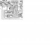
Here is the pic of the V-I board's part:
OK if the problem is in just misprinting, but it is not. There is something more to it, which I don't know and need help for it.
Also, there is a "problem" wit BIAS setting, using the manual. The answer is given here: http://www.diyaudio.com/forums/solid-state/41288-overheating-low-bias-2.html#post1591407 The point is, that the manual is not complete, and there are some steps omitted in it. I believe that for the V-I BALANCE, the situation is similar.
The real situation on the amplifier is like this:
On the EQ board, there are TP and TP2
On the V-I board, there are TP3 and TP4
Test points fot BIAS, on the main amp: TP5 and TP6;
On the PowerSupply board TP7
There are only 6 trimmer pots on the amp: 2 for bias, on the main amp, labelled RT301 and RT351;
2 for EQ board: RT101 and RT151
2 on the V-I board: RT201 and RT251.
Here is the pic of the V-I board's part:
An externally hosted image should be here but it was not working when we last tested it.
OK if the problem is in just misprinting, but it is not. There is something more to it, which I don't know and need help for it.
Also, there is a "problem" wit BIAS setting, using the manual. The answer is given here: http://www.diyaudio.com/forums/solid-state/41288-overheating-low-bias-2.html#post1591407 The point is, that the manual is not complete, and there are some steps omitted in it. I believe that for the V-I BALANCE, the situation is similar.
Last edited:
As I said - dumb question. Did you check voltages on legs of adjusting pots? It doesn't seem to have missing steps but, as you point out, it certainly could.
Yes. I did. I'm not close to the amp right now, so, I can't measure the voltage on legs of RT251 and RT201, but, as I recall, I was able to adjust for 0mV on 1 of the 3 legs of the pot (If this makes any sense to you). I don't remember the voltages of the other legs. I will post here again in a day or two, when I will be able to work with the amp again.
As I said - dumb question. Did you check voltages on legs of adjusting pots? It doesn't seem to have missing steps but, as you point out, it certainly could.
Now I checked it up for good. RT201 and 251 has both +600mV and -600mV on their legs. This Voltage is, as you look at the photo of that pcb, at the top 2 (4) legs. The bottom leg of RT201 and 251 is about 0V. Is this correct?
the bias test point is between test points and not from any test point to ground
dc offset is between test point and ground
look at the instructions in the manual ... you obviously missed that
( suggest: find a more modest nick name )
read this also :http://www.diyaudio.com/forums/solid-state/136261-vintage-amplifier-repair-upgrade-manual.html
dc offset is between test point and ground
look at the instructions in the manual ... you obviously missed that
( suggest: find a more modest nick name )
read this also :http://www.diyaudio.com/forums/solid-state/136261-vintage-amplifier-repair-upgrade-manual.html
No, that's exactly how I measured: BIAS across test points and BALANCE between test point and ground. As indicated in schematic.the bias test point is between test points and not from any test point to ground
dc offset is between test point and ground
look at the instructions in the manual ... you obviously missed that
The results of measurements of the voltages in my previous post above are between any leg of the trimmer and ground. So, between leg1 and GND is 600mV, leg2 and GND -600mV and leg3 and GND 0mV.
By turning the trim pots RT201 and RT251 , I set them at 0mV at third leg. But, the voltage should be measured on test point and not on the leg.
😉( suggest: find a more modest nick name )
Very nice manual, thanks. I read it whole on my phone.
- Status
- Not open for further replies.
- Home
- Amplifiers
- Solid State
- Vintage SONY TA-F555ES DC adjustment question