Hello!
I want to build a tiny transistor amplifier, using very few, cheap and commonly available parts (no opamps or ICs). Basically something with regular TO-92 style transistors, or similar. Powered by a simple 9-12 volt wall wart. Just a power switch and a passive volume control. Sound quality is not important, but a bonus. Basically I want to build something like the amp found in cheap computer speakers.
I've been looking around and cannot really find what I need... Does anyone know where I can find a pre-made schematic for something like this?
Thanks!")
I want to build a tiny transistor amplifier, using very few, cheap and commonly available parts (no opamps or ICs). Basically something with regular TO-92 style transistors, or similar. Powered by a simple 9-12 volt wall wart. Just a power switch and a passive volume control. Sound quality is not important, but a bonus. Basically I want to build something like the amp found in cheap computer speakers.
I've been looking around and cannot really find what I need... Does anyone know where I can find a pre-made schematic for something like this?
Thanks!
Basically I want to build something like the amp found in cheap computer speakers.
but that would be an opamp/IC
Hello!
I want to build a tiny transistor amplifier, using very few, cheap and commonly available parts (no opamps or ICs). Basically something with regular TO-92 style transistors, or similar. Powered by a simple 9-12 volt wall wart. Just a power switch and a passive volume control. Sound quality is not important, but a bonus. Basically I want to build something like the amp found in cheap computer speakers.
I've been looking around and cannot really find what I need... Does anyone know where I can find a pre-made schematic for something like this?
Thanks!
Hi,
Your misguided. You can't build an amplifier just using small signal transistors.
Its stops being simple very quickly when you realise just how rubbish your
simple amplifier is compared to simple IC circuits that have been around
for years, and for good reason, they are simple, and they work well.
No computer speakers use an amplifier of your description. The latest use
mini class d driven from the 5V supply of USB ports. Older ones almost
exclusively use chip-amps. With a 12V supply your talking car audio
and there is simply loads of options, around 5W / 4 ohms for a
simple circuit and up to 20W for bridged into 4 ohms.
IMO just buy a cheap kit off e-pray.
rgds, sreten.
Last edited:
Member
Joined 2009
Paid Member
- this is DIY, no kits! There's a truck load of web sites with simple amps. And power devices may not be so critical if listening to small speakers at low volume - when I listen to my computer speakers I'm guessing they're playing at 1/8 W. But it is a stretch when a couple of power transistors can be had cheaply these days - even a pair of old 2N3055's from an old power supply or something.
http://www.electro-tech-online.com/datasheets-manuals-parts/12407-i-need-datasheet.html
http://musicouch.com/instruments/st...-mini-amplifier-for-tuner-or-simple-receiver/
http://www.electro-tech-online.com/datasheets-manuals-parts/12407-i-need-datasheet.html
http://musicouch.com/instruments/st...-mini-amplifier-for-tuner-or-simple-receiver/
Last edited:
Hi,
Your misguided. You can't build an amplifier just using small signal transistors.
Its stops being simple very quickly when you realise just how rubbish your
simple amplifier is compared to simple IC circuits that have been around
for years, and for good reason, they are simple, and they work well.
You miss a good reason he may be requesting this sort of information - to understand how amplifier circuits WORK. A chip tells you nothing in this regard, it is just a "black box full of tricks".
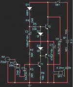
Here is an original proposition.
Despite its simplicity, it even manages to include an auto-bias circuit:
Indeed the original proposal !
Just a little bit of practice, not a very good agreement.
This refers to the thermal instability of the mid-point scheme +6V, as well as the instability of the change in power voltage within +/-10%.
Minimal changes to make everything Ok!:
Resistor R4 = 15 kilohms.
And to add R7 = 75 Ohm emitter in Q4.
Sorry, I dont speak English,
use a google translate.
Last edited:
Indeed the original proposal !
Hi,
Yeah .... build it. Try that test into a real speaker. One dead amplifier.
The output devices are about 1/2W each and simply will expire if they
haven't already due to to the standing current and thermal runaway.
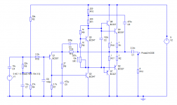
Here is a circuit that shouldn't blow up,
and shouldn't hum* (good ripple rejection) :
Bolt something to each output device as a heat sink.
IMO you should use 0.47R output emitter resistors.
Should get about 4 watts into 4 ohms.
rgds, sreten.
* too much ........
model it using the free TinaTi circuit emulator
Last edited:
Did you actually try it?Hi,
Yeah .... build it. Try that test into a real speaker. One dead amplifier.
Or is it just an informed opinion?
Last edited:
If you go back to take another look at my circuit it is basically a 4-transistor architecture but with a bias transistor and parallel outputs. Actually you could use a single pair of Zetex devices but these cost more. You could use a single pair of BC337/BC327 but they suffer a little gain loss at 500 mA, buit you could increase the driver current. The circuit is capable of producing 1W from a 9V supply with an excellent frequency response and very low crossover distortion because of the high speed of the output transistors. In fact this alone makes such a simple circuit sound better than many amps using slow output transistors and even IC amps which have Miller stabilisation capacitors.
Nice classic design, quite robustly dimensioned. I am sure it delivers the goods.If you go back to take another look at my circuit it is basically a 4-transistor architecture but with a bias transistor and parallel outputs. Actually you could use a single pair of Zetex devices but these cost more. You could use a single pair of BC337/BC327 but they suffer a little gain loss at 500 mA, buit you could increase the driver current. The circuit is capable of producing 1W from a 9V supply with an excellent frequency response and very low crossover distortion because of the high speed of the output transistors. In fact this alone makes such a simple circuit sound better than many amps using slow output transistors and even IC amps which have Miller stabilisation capacitors.
I have built many similar amplifiers in the early seventies, the first ones with Ge transistors, and I was very pleased and amazed at the quality, compared to what was routinely available at the time.
About that golden standard of an amplifier, I am less sure: to begin with, it manages to achieve a positive PSRR (I mean, it amplifies the supply noise) of +6dB or thereabout, a feat I have never seen before, and it begins to clip at ~150mW output power.Here is a circuit that shouldn't blow up,
and shouldn't hum* (good ripple rejection) :
My own humble proposal only has a relatively poor -40dB+ rejection, but at least, it's rejection, not amplification.
That is an impossibilty with the autobias circuit: in fact, Q1 and Q2 could be replaced by Ge transistors and no other adaptation, and the thing would still not go into thermal runaway, even at 75°C and without any heatsink.if they
haven't already due to to the standing current and thermal runaway.
The same cannot be said of other amplifiers....
The circuit I gave is absolutely minimalist, but it does work, and it is incredibly resilient.
As it is, the (audio) quality is not very good, but with an antisaturation diode on the control transistor it can be substantially improved, and if quality is the first objective (not that of the OP), some others mods can be brought, keeping the incredible thermal robustness.
Hint: the total quiescent current is approximately twice the VAS bias curent, and it diminishes when the OP transistor's temperature increases.
I think I know where the ripple amplification on the amp posted by sreten comes from. The upper 2N3906 (VAS) base voltage is cleaned up, but there's full ripple on the emitter and hence on B-E voltage. Oops. Ripple should still be reduced by loop gain though (at least the part contributed by input and output Qs).
The output stage on that one is pretty decent though. I'd combine it with a pnp input / npn VAS as used by john_ellis (well, in fact, his amp would also work fine when beefed up with one pair of BD139/140 and 0.47R emitter Rs). VAS V_be is all ground referenced there. So that's why pnp inputs were popular in the olden days.
The output stage on that one is pretty decent though. I'd combine it with a pnp input / npn VAS as used by john_ellis (well, in fact, his amp would also work fine when beefed up with one pair of BD139/140 and 0.47R emitter Rs). VAS V_be is all ground referenced there. So that's why pnp inputs were popular in the olden days.
Last edited:
VAS V_be is all ground referenced there. So that's why pnp inputs were popular in the olden days.
That, and all the good VAS transistors were NPN.
> Here is an original proposition.
That's a brain-fork, but it will work.
It will work exceptionally well for the number of parts.
It expects some ratio hFE(Q3):hFE(Q1). The suggested types may give an output idle bias that varies 5:1, which is fuly acceptable here.
Heat (even leakage) have very little effect. Rise of Q3 hFE is cancelled by rise of Q1 hFE. If Q3 Q1 leak real bad but in similar amounts, they cancel.
Vbe of Q3 Q1 Q2 does not matter (which is my mind-fork problem).
Output center-point voltage depends on Vbe and hFE of Q4, and will drop with temperature. Unless Q4 is in the oven it won't go off a happy operating point. If supply voltage changes slightly, center point tends to change in the right direction but not enough. For a large change like 9V, R4 is there for tweaking.
There's no outright short-protection but it may stand many shorts. When output is shorted the bootstrapping fails. If shorted with large input signal you can probably kill it. I see the "power" transistors are 7 cents.... not worth crying over.
NFB is small, especially through crossover... but astonishing to have any NFB at this voltage and current gain and efficiency with just a dozen parts.
My all-time favorite small amp had a couple more parts and many of the same "flaws". I think I had as much listening pleasure from that amp as any other. I had to sit close... but same as I sit to my PC speakers 40+ years later.
- Status
- This old topic is closed. If you want to reopen this topic, contact a moderator using the "Report Post" button.
- Home
- Amplifiers
- Solid State
- Would like to build super simple mini transistor amplifier