I have built small amps for my kids & incorporated a MiniDSP unit into them so I can use it to control a sub as well. The problem I would like to solve is how to turn the DSP on first (as it make horrible noises) and hold the DSP on for a few seconds even if we have a power outage (happens a bit around here).
My electronics knowledge is limited & would greatly appreciate a bit of help.
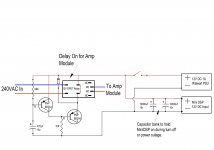
The DSP is powered by a separate 12VDC 1A Walwart PSU. To hold the DSP on I was planning on installing a capacitor bank to keep the unit on if the power failed or on normal turn off. I am not sure if it is ok to do this as per my drawing, can anyone advise me please.
The turn on circuit for the amp is copied from the WEB so I assume its kosher.
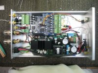
As you can see I dont have a lot of room to work with.
My electronics knowledge is limited & would greatly appreciate a bit of help.
The DSP is powered by a separate 12VDC 1A Walwart PSU. To hold the DSP on I was planning on installing a capacitor bank to keep the unit on if the power failed or on normal turn off. I am not sure if it is ok to do this as per my drawing, can anyone advise me please.
The turn on circuit for the amp is copied from the WEB so I assume its kosher.
As you can see I dont have a lot of room to work with.
Attachments
Last edited:
So many approaches to this kind of issue.
Doing as sofaspud suggests and incorporating a diode is essential as without the DSP supply discharges back into the PSU circuitry. In practice it may or may not make much difference depending on the loading.
A diode across the 68K will help discharge the cap quicker on power off so that the "reset action" works straight away again.
These kind of circuits can be a bit tricky and indeterminate. The second transistor collector to go to ground of course. First transistor. A 470uF from base to ground is a "short" as it initially charges pulling all the current through the B-E junction. Not good imo. It's all very unpredictable in use.
How about a proper speaker delay instead ? One that gives a few seconds delay at power up and is able to detect short mains drop outs and so always giving the full delay time.
The Vbe of that left most PNP is enormous (12Vbe) at the moment of switch on.
The collector current is limited by the 10k load to -12V (~1.2mApk).
The base current has no current limiter !!!
Is that a bad thing?
Should I do something differently?
The DSP is powered by a separate 12VDC 1A Walwart PSU.
How about using a 12V battery.
How about using a 12V battery.
Then I'd need a charger, also I need to cram it into the existing case.
")
The 555 timer IC can easily be configured to give you a delayed turn-on, the duration of which is set by the resistance of a single resistor. Also, the 555 IC and associated resistors and capacitors draws negligible current.
Probably you can find a suitable schematic diagram by searching for "555 timer circuits".
At the present time I can't post graphics here as I don't have a web address for them. Otherwise I would post the circuit.
-Pete
Probably you can find a suitable schematic diagram by searching for "555 timer circuits".
At the present time I can't post graphics here as I don't have a web address for them. Otherwise I would post the circuit.
-Pete
Is that a bad thing?
Should I do something differently?
It's a bad thing and yes.
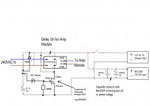
Something like this is easy. I've just made this circuit up but all the values are in the right ball park and will work. The 47uF cap can be altered to give a different delay. The zener just means the voltage across the cap has to rise a bit more (4.7 volts more) before the FET conducts.
The 100K and 47uf charge at switch on. When the voltage across the cap exceeds 4.7 volts plus the turn on volts of the FET (around 4 volts) then the relay pulls in.
Using a FET means we need no equivalent of "base current" and so we can design using high value resistors and small caps.
The diode across the 100k pulls the voltage on the cap down quickly at power off.
Edit... and remember to include and try the diode sofaspud mentioned
Attachments
Someone might have a more sophisticated watchdog circuit, but your idea is correct. The caps have to hold enough charge for the load+time, but I'm not sure what that is. Put a Schottky diode to the left of the cap bank to force the voltage to the DSP.
Is there a reason it needs to be a Schottky diode?
It's a bad thing and yes.
Something like this is easy. I've just made this circuit up but all the values are in the right ball park and will work. The 47uF cap can be altered to give a different delay. The zener just means the voltage across the cap has to rise a bit more (4.7 volts more) before the FET conducts.
The 100K and 47uf charge at switch on. When the voltage across the cap exceeds 4.7 volts plus the turn on volts of the FET (around 4 volts) then the relay pulls in.
Using a FET means we need no equivalent of "base current" and so we can design using high value resistors and small caps.
The diode across the 100k pulls the voltage on the cap down quickly at power off.
Edit... and remember to include and try the diode sofaspud mentioned
Wow thank you, thank you all.
Shottky diodes have a lower forward volt drop. Does that matter ?
If the DSP take the 12 volts from a wall wart and regulates it again to say 5 volts then it makes no difference what you use.
If some of the DSP circuitry does actually run directly off 12 volts (meaning the audio side of things) then the diode directly alters that 12 volt supply.
A normal silicon diode would reduce the 12 volts to around 11.3 (ish) and a Shottky around 11.8 volts. It probably makes no difference in practice. And is the PSU giving 12.000 volts anyhow. It won't be that critical.
Shottky diodes have a lower forward volt drop. Does that matter ?
If the DSP take the 12 volts from a wall wart and regulates it again to say 5 volts then it makes no difference what you use.
If some of the DSP circuitry does actually run directly off 12 volts (meaning the audio side of things) then the diode directly alters that 12 volt supply.
A normal silicon diode would reduce the 12 volts to around 11.3 (ish) and a Shottky around 11.8 volts. It probably makes no difference in practice. And is the PSU giving 12.000 volts anyhow. It won't be that critical.
Your a fountain of knowledge, thank you, I will go with the Shottky to preserve as much voltage as possible as the MiniDSP says it needs 12V.
Thanks again
The reason that D2 needs to be high voltage is because it is there to kill the back EMF generated by the relay as it de-energises.
To see what you are up against. Simply take a 12V relay and connect it across a 12V supply. When you disconnect it notice the nice big spark that you get.
To see what you are up against. Simply take a 12V relay and connect it across a 12V supply. When you disconnect it notice the nice big spark that you get.
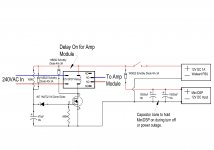
D2:
no.
the back emf reaches high voltages when one does not let the "continuation" of the current flow.
If the diode is in place (or a Zener) then the current continues to flow and the back emf never exceeds the voltage that the circuit presents when that level of current is asked to pass around the circuit.
If the voltage is set by a diode, then the back emf is limited to the existing voltage across the relay coil at the moment just at turn off plus Vf or ~12.6Vdc. The coil resistance will limit that continuing current to ~ the same value it was just prior to turn off.
You don't need a high voltage diode.
The diode or Zener only needs to resist the maximum worst case supply voltage to the relay coil, maybe 12Vdc +25%.
D1:
no.
the diode is there to discharge the timing cap quickly after turn off.
D3:
no.
the diode is there to prevent the DSP temporary supply keeping the timing circuit powered up after turn off. It has been suggested that the problem may go away if the DSP keeps running for a short time after turn off and those caps are only there to provide that temporary power for the DSP alone.
D1, can be 1n4001
D2 can be 1n4001, or 15V Zener, or 1n914, or 1n4148 (yes, these signal diodes will easily pass the kickback from a small audio relay)
D2 may benefit from being a very low Vf depending on the power requirements of the DSP.
no.
the back emf reaches high voltages when one does not let the "continuation" of the current flow.
If the diode is in place (or a Zener) then the current continues to flow and the back emf never exceeds the voltage that the circuit presents when that level of current is asked to pass around the circuit.
If the voltage is set by a diode, then the back emf is limited to the existing voltage across the relay coil at the moment just at turn off plus Vf or ~12.6Vdc. The coil resistance will limit that continuing current to ~ the same value it was just prior to turn off.
You don't need a high voltage diode.
The diode or Zener only needs to resist the maximum worst case supply voltage to the relay coil, maybe 12Vdc +25%.
D1:
no.
the diode is there to discharge the timing cap quickly after turn off.
D3:
no.
the diode is there to prevent the DSP temporary supply keeping the timing circuit powered up after turn off. It has been suggested that the problem may go away if the DSP keeps running for a short time after turn off and those caps are only there to provide that temporary power for the DSP alone.
D1, can be 1n4001
D2 can be 1n4001, or 15V Zener, or 1n914, or 1n4148 (yes, these signal diodes will easily pass the kickback from a small audio relay)
D2 may benefit from being a very low Vf depending on the power requirements of the DSP.
Last edited:
Think Andrew has covered most points here.
Experiment with value of 470uF cap. In post #9 I changed it 47uF. At 470uF you might be waiting quite a while
Time constant is C*R and defined as the time for the cap to charge to around 63% when fed via a resistor. If you think about it, a resistor does not charge the cap linearly because as the voltage across the cap rises there is less voltage left across the resistor to keep charging the cap. It takes around 5T for the cap to fully charge.
So "T" for a 47uf and 100k is around 5 seconds give or take. The zener will only conduct at over 4.7 volts and the FET needs around 4 volts across the G-S junction for the relay to click in.
So it's all in the right ball park I think time wise. If you want a longer delay try a 68 or 100uf cap.
- Status
- This old topic is closed. If you want to reopen this topic, contact a moderator using the "Report Post" button.
- Home
- Amplifiers
- Solid State
- Delay On/Off Setup