Hi,
I've been out of the audio hobby for a while and lately i decided to get my old gear back together. I still had my LS3/5A on the attic, so all i needed was a philips cd with 1541 Dacs, an Audioanalyse P90 and a set of Audioquest LS Cables.
This set played excellent, but i sold about everything 15 years ago, exept the LS3/5A's. I am gonna bypass the input board and and the volume / balance section of this amp.
Last week I found a used Duson PA75, and I payed 225,- Euro for it, not too bad. (i knew the Duson PA75 is practicly identical to the P90).
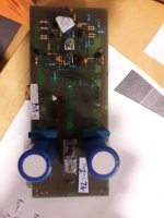
A few things i noticed when i hooked up the Duson. The sound was ok, but not what I expected. Too, the unit stayed ice cold. I opened the Duson to do some measurements.
Uploaded with ImageShack.us
I've been out of the audio hobby for a while and lately i decided to get my old gear back together. I still had my LS3/5A on the attic, so all i needed was a philips cd with 1541 Dacs, an Audioanalyse P90 and a set of Audioquest LS Cables.
This set played excellent, but i sold about everything 15 years ago, exept the LS3/5A's. I am gonna bypass the input board and and the volume / balance section of this amp.
Last week I found a used Duson PA75, and I payed 225,- Euro for it, not too bad. (i knew the Duson PA75 is practicly identical to the P90).
A few things i noticed when i hooked up the Duson. The sound was ok, but not what I expected. Too, the unit stayed ice cold. I opened the Duson to do some measurements.
An externally hosted image should be here but it was not working when we last tested it.
Uploaded with ImageShack.us
Last edited:
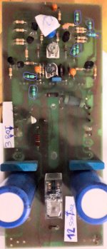
A couple of things I noticed right away when opening the unit. Someone had been soldering in the unit before. There were some really bad solderjoints on some PCB's.
But anyway. I measured the current in both endstages, and it was 50 mA via T13, and 22mA via T14. I also noticed that there was 145mV on the speaker terminal on the richt channel. The offset was simple to correct with R14 pot, the Bias on the endstages was increased with R19 to 100mA per TIP (although i couldnt get the same bias on T13 and T14, probably because the were by far from matched)
Sadly i had to cough and accidently i sparked the PCD, so now t13 and 14 are gone, will pick up some new this afternoon.
Uploaded with ImageShack.us
Uploaded with ImageShack.us
But anyway. I measured the current in both endstages, and it was 50 mA via T13, and 22mA via T14. I also noticed that there was 145mV on the speaker terminal on the richt channel. The offset was simple to correct with R14 pot, the Bias on the endstages was increased with R19 to 100mA per TIP (although i couldnt get the same bias on T13 and T14, probably because the were by far from matched)
Sadly i had to cough
and accidently i sparked the PCD, so now t13 and 14 are gone, will pick up some new this afternoon.An externally hosted image should be here but it was not working when we last tested it.
Uploaded with ImageShack.us
An externally hosted image should be here but it was not working when we last tested it.
Uploaded with ImageShack.us
looks similar to this brand:
http://www.diyaudio.com/forums/soli...pa-60-pa60-power-amp-where-get-schematic.html
http://www.diyaudio.com/forums/solid-state/158854-audio-analyse-french-made-amp.html
http://www.diyaudio.com/forums/soli...pa-60-pa60-power-amp-where-get-schematic.html
http://www.diyaudio.com/forums/solid-state/158854-audio-analyse-french-made-amp.html
Last edited:
To be a bit more precise:
- BC 639/640 should be 1N1550/1551
- BD 230/231 should be MJE340/350
- the bias circuit around D4/D5 is a classic transistor based one with a BD139 on the heatsink. This one is critical to maintain thermal stability
- C7 should be much smaler (10nF)
- R36 has a 47E/10pF series circuit in parallel (critical to avoid oscillation)
Hi
Found a Duson PA-75 damaged by lightning I think. As I am a newbie I don´t know these parts marked in the photo attached. If anyone could tell me I could try my luck. Thx.
mike
What you really need is a circuit diagram. Your image is to blurry to make out, however they do all 'look' the same from what I can make out.
Have you tried measuring them ? Do they all read very low resistance or do they all read open circuit ? They could be either low value resistors or small encapsulated inductors.
I can see other obvious damage on that PCB.
Have you tried measuring them ? Do they all read very low resistance or do they all read open circuit ? They could be either low value resistors or small encapsulated inductors.
I can see other obvious damage on that PCB.
The white paper under the board fools the camera and makes the board dark. The underexposure makes the image noisy. I do not think there is enough light for your camera.
Here's an artificially enhanced image, but it is still "blurry".
I have a guess that the mystery parts are "ZeroOhm" jumpers. If so, they are not likely to be your problem. But it is odd to see so many ZeroOhms on such a simple build.
Here's an artificially enhanced image, but it is still "blurry".
I have a guess that the mystery parts are "ZeroOhm" jumpers. If so, they are not likely to be your problem. But it is odd to see so many ZeroOhms on such a simple build.
Attachments
- Status
- This old topic is closed. If you want to reopen this topic, contact a moderator using the "Report Post" button.
- Home
- Amplifiers
- Solid State
- Duson PA75 repair