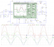
Primarily it lowers the impedance around the bias transistor so that rail sag doesnt influence the bias current much. Higher value is better but no need to go overboard, 10 to 100 uf is perfect. Other way of better results is use of darlington, cfp or super beta transistor. These bring even more improvement but a added advantage of super beta is higher temperature sensitivity and faster response.
Another way to lower the impedance was brought to the forums attention by Keatoken, instead of a cap accross emitter collector use one accross base collector of the transistor (parrallel with top voltage divider resistor). In the case of impedance its the best performing.
Another way to lower the impedance was brought to the forums attention by Keatoken, instead of a cap accross emitter collector use one accross base collector of the transistor (parrallel with top voltage divider resistor). In the case of impedance its the best performing.
One of the problem with this cap, particularly when it is large value, is its inverse peak detection effect: at higher power levels, the transistors bases steal more of the charging current, and as a result, the voltage across it decreases, because of the non-zero impedance of the bias network.
And the reason why the capacitor was installed in the first place happens to be this non-zero impedance. See?
That's one of the reasons to opt for a good automatic bias. Class i thread is one of the examples of what can be achieved using these techniques.
And the reason why the capacitor was installed in the first place happens to be this non-zero impedance. See?
That's one of the reasons to opt for a good automatic bias. Class i thread is one of the examples of what can be achieved using these techniques.
- Status
- This old topic is closed. If you want to reopen this topic, contact a moderator using the "Report Post" button.
