LPUHP underneath heat spreader complete ...
See attached pics")
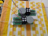
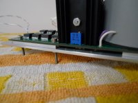
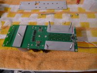
25mm wide, 3mm thick alu bars under each row of buffers. An extra 3mm bar under the sumr tx and a 1.6mm thick alu bar to draw heat from the opamp. Keratherm Red between alu and pcb/opamps and thermal paste between small alu bars and the 3 x 50mm wide, 3mm thick alu sheets that tie it all together.
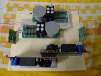
For good measure I've included a gratuitous photo of my planned 4ch case layout with DPS600+lateral fet LME49830 Class AB The Wire amps. The manila folder is the same size as the available floor space.
Chris
See attached pics
25mm wide, 3mm thick alu bars under each row of buffers. An extra 3mm bar under the sumr tx and a 1.6mm thick alu bar to draw heat from the opamp. Keratherm Red between alu and pcb/opamps and thermal paste between small alu bars and the 3 x 50mm wide, 3mm thick alu sheets that tie it all together.
For good measure I've included a gratuitous photo of my planned 4ch case layout with DPS600+lateral fet LME49830 Class AB The Wire amps. The manila folder is the same size as the available floor space.
Chris
Attachments
Crikey! Those are some pimped out heatsinks!
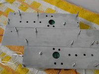
Speed holes and all
You'll definitely have the happiest buffers of the group.
Overall it's a very elegant solution to the heatsinking problem, which was something that took a lot of effort with the "production" version.
Keep up the good work!
superR:
It's unlikely that I will be offering blank boards, and it's equally unlikely that anyone who wants to maintain sanity would want to hand solder that many buffers and bypass caps.
In all, there are 32 buffers per channel, for a total of 64 buffers in a stereo pair. Each buffer has a pair of bypass caps, which brings the solder joint count up to 640 joints just for the buffers. I've done it once, and I will never do it again. It's more monotonous torture than DIY.
The other issue is that if I sell the bare boards, people expect them at cost, which is not realistic or fair for a product that has undergone this level of refinement. It's also unfair to anyone who buys the finished product as it promotes the idea that a piece of audio equipment is only worth what the BOM cost is.
Things are still not entirely final, but expect some pictures in the near future. I'm planning on showing them at the suitably humble Ottawa audio DIY gathering in April, so things will be moving pretty quickly from here on in.
Cheers,
Owen
Here at DIY that is how much it's worth. But in the rest of the world a piece is worth what someone will pay. If you can ask for, and get, £10,000 then that how much it's worth to the right person. It might be a door stop to anyone else.it promotes the idea that a piece of audio equipment is only worth the BOM cost
The problem any inventor faces is recovering cash from intellectual property.
Last edited:
Here at DIY that is how much it's worth. But in the rest of the world a piece is worth what someone will pay. If you can ask for, and get, £10,000 then that how much it's worth to the right person. It might be a door stop to anyone else.
Therein lies the problem...
It's very difficult to have it both ways. Your average consumer, who has no interest in putting anything together should evidently expect to pay more for a completely finished and tested product. The problem is with the first part of your statement, which unfortunately is quite true. The BOM does not include development costs, or the costs of the expertise required to make a finished product. I think everyone here could draw up a basic schematic based on what I've said above, but going from that to a very good performing amplifier is not trivial. It's also not something that should be expected for free.
It think to successfully have it both ways, you need to tread a fine line similar to what Nelson does. He has Pass Labs, which offers excellent products at upper-market prices, and essentially gives people almost unlimited access to his expertise here on diyAudio. You'll notice, however, that he does not offer his Pass Labs products in kit form at cost, as that would surely impact finished product sales, and setup an unfair pricing structure.
Anyhow... I've been struggling with all of this, trying to come up with a fair compromise, but it's not a simple issue and it doesn't have a simple solution.
Cheers,
Owen
Is there a lot of noise from that many paralleled buffers? Recalling that you'd found an unacceptable amount of noise with your IEM's with just two paralleled buffers.
The short answer is yes... the noise floor from 32 buffers is higher than the noise floor from 1 buffer. It's the price you pay for getting 50W of output into 8 ohms.
Would I use the new version to drive IEM headphones? Absolutely not... a single buffer is ideal for that.
Will a single buffer drive an 8 ohm loudspeaker to usable levels? Again, absolutely not, for that you need many more buffers.
What's wonderful about this setup is that if you need 50W, then by nature, your system will be less sensitive to noise. If you only need 1W, there's a good chance your system is far more noise sensitive. In the case of IEM headphones, adding parallel buffers gives you nothing except higher noise, which seems a waste to me.
You should always use just what you need, and never more. Using more always comes with a downside, so you need to be able to justify it.
Cheers,
Owen
Actually that's not the case OPC. The noise from paralleled semiconductors REDUCES by the square root of N, where N is the number of paralleled devices, compared to a single device.
So for four paralled devices the noise reduces by SQRT (4) = 2 = 6 dB.
For 32 paralleled devices it reduces by SQRT (32) = 5.65 = 15 dB
That's why low noise moving coil headamps use lots of paralleled transistors at the input stage.
So for four paralled devices the noise reduces by SQRT (4) = 2 = 6 dB.
For 32 paralleled devices it reduces by SQRT (32) = 5.65 = 15 dB
That's why low noise moving coil headamps use lots of paralleled transistors at the input stage.
Last edited:
Gopher,
That is true of discrete transistors under the correct conditions, but it is not true of integrated circuits like the buffer we're talking about.
In this case, it's more akin to paralleling op-amps, which does not result in lower noise.
Regards,
Owen
Edit: It should also be noted that practical considerations start to quickly outweigh the benefits of parallel discrete transistors when the numbers start creeping over 4. If you have 32 parallel transistors on an very noise sensitive input, there will be serious layout compromises made which will likely null, or possibly worsen the performance relative a layout with far fewer devices.
Theoretical noise reduction is one thing, practical noise reduction is another
It's part of the reason simulations rarely make accurate predictions of noise in a real circuit.
Last edited:
Are you sure? From my experience paralleling op-amps does reduce noise.
Linear Technology Circuits - Paralleling Amplifiers to Reduce Noise
Op Amp Applications Handbook - Walt Jung - Google Books
Linear Technology Circuits - Paralleling Amplifiers to Reduce Noise
Op Amp Applications Handbook - Walt Jung - Google Books
Would it have worked just about as well to have used the input stage of one of these buffers and then just used multiple paralleled output transistors? It is about avoiding having to find transistor matches.
With the Meridian 605 they used an Op-Amp with pin 6 going to the centre of cascaded driver transistors and the power rails directly fed the MOSFET gates. The transistors then shunted the gates down when output was needed. The MOSFETs are connected reversed with power rails to Source. Seems very simple.
How would your 50Watts compare to an Audia Flight class A 50Watts driving 93dB sensitive Tannoy speakers older version of
these twin 10 inchers? Apparently they drop to 2 Ohms in places. A friend has these and has found some amplifiers can't supply the control and the speakers boom but this Audia, weighing in at 66lb, appears to be OK.
Last edited:
That depends... what is your dominant source of noise in the overall circuit?
In the case of these buffers, they are nested within the feedback loop of another op-amp, which is the dominant source of the noise in the circuit. You can parallel to your heart's content, and there will not be any additional noise benefit.
What there will be is longer traces and a less ideal layout, both of which result in more noise.
It all depends on what you're doing, and what the circuit looks like. In the case of the example in the Linear datasheet, the answer is yes, noise will be reduced. It won't be quite as ideal as stated, and I would imagine that given a low enough noise op-amp you will probably do more harm than good by adding several in parallel.
Again, there's theoretical, and there's the real world. I can build you a differential SPICE circuit that has absolutely no second order harmonic distortion, but if you build it, you'll see that's not the case.
Cheers,
Owen
So the recommended transformer, L01-6363 is OOS at Digikey, and not due for 1.5 months.
The lower voltage L01-6362 is also OOS, but is due in a few days.
Since I don't the full 18VDC rails, I plan to use the 6362, and will live with around 15VDC rails.
From what I read here, that will also reduce the heatsinking requirement, and make it more likely that I can just used the BOM heatsink, with maybe a RAM heatsink thrown in.
Randy
Therein lies the problem...
It's very difficult to have it both ways. Your average consumer, who has no interest in putting anything together should evidently expect to pay more for a completely finished and tested product. The problem is with the first part of your statement, which unfortunately is quite true. The BOM does not include development costs, or the costs of the expertise required to make a finished product. I think everyone here could draw up a basic schematic based on what I've said above, but going from that to a very good performing amplifier is not trivial. It's also not something that should be expected for free.
It think to successfully have it both ways, you need to tread a fine line similar to what Nelson does. He has Pass Labs, which offers excellent products at upper-market prices, and essentially gives people almost unlimited access to his expertise here on diyAudio. You'll notice, however, that he does not offer his Pass Labs products in kit form at cost, as that would surely impact finished product sales, and setup an unfair pricing structure.
Anyhow... I've been struggling with all of this, trying to come up with a fair compromise, but it's not a simple issue and it doesn't have a simple solution.
Cheers,
Owen
Owen,
I have actually been thinking about this for a while independently of this topic coming up here. I think if someone wants to de-value design work to the cost of a pcb manufactured in a short run, then let them buy second class ebay designed pcbs and let them enjoy their delusion, they're not in it for performance but just the need to say they built something.
Do people think that the Orion speaker is only worth as much as the cost of the drivers and some timber? Do people think that Geddes' Abbey is only worth the manufacturing cost of his custom CPLD baffle+waveguide? Why is it any different for a circuit board?
In DIY I actually am only aiming to get the best combination of equipment to minimise/control the number of compromises in my system. If that means outsourcing some menial soldering work and paying a guy who has designed an amp that is better than normal, I'm not going to lose a moment's sleep.
So the recommended transformer, L01-6363 is OOS at Digikey, and not due for 1.5 months.
The lower voltage L01-6362 is also OOS, but is due in a few days.
Since I don't the full 18VDC rails, I plan to use the 6362, and will live with around 15VDC rails.
From what I read here, that will also reduce the heatsinking requirement, and make it more likely that I can just used the BOM heatsink, with maybe a RAM heatsink thrown in.
Randy
Randy,
I am not so sure that you don't want higher rails, depends on your target output I guess but off top of my head I'd have though that keeping the rails high would help in driving your high impedance load.
In terms of heatsinking, it depends a lot on where you're using it. If ambient temps are low then really these amps don't need much heatsinking. I know that my amps may get left on and that we get ambient temps here pushing 35-38degC most summers so when these are inside a case with class ab amps, the temp inside the amp enclosure will be ... quite warm, so that's why I went to extra effort. With normal temps without extra heat dumped from nearby gear I think the BOM heatsink is plenty though probably limited by the thermal conductivity of the LME49600 chip cases which is why I went under the pcb as the heat will come through the pcb more freely than the plastic chip cases. The opamps have only ever been reported to be a bit toasty by feel, in reality they are rated to run pretty warm and probably aren't an issue at all. I was going to leave them alone, but I ended up with them being covered by the alu that is taking heat off the buffers, then I worried about airflow in the 3mm gap and decided to put the 1.6mm bar to the opamps and a few 'speed holes' for extra ventilation. I decided the diodes would benefit from a bit more ventilation so overcompensated a touch with the hole under them!
Crikey! Those are some pimped out heatsinks!
Speed holes and all
You'll definitely have the happiest buffers of the group.
Overall it's a very elegant solution to the heatsinking problem, which was something that took a lot of effort with the "production" version.
Keep up the good work!
Thanks Owen, cannot wait to have them all up and running, that'll be a while yet. I am starting to think of this 4ch amp as 'Temple of Wire'. I really need to get back to the auto-bias pcb design for the LME amp soon but those little alu bars took a lot more time than I first expected. I only have a hacksaw, a hand drill and some sandpaper so making those was certainly doing it the hard way. Hope those buffers appreciate it!!
Cheers,
Chris
Owen,I use a 103dB 1W/1m midbass, and a 116dB 1W/1m compression driver to listen for detectable noise.
Have you tried current drive with your midbass driver? (or just using a series resistor to simulate it)
Randy,
I am not so sure that you don't want higher rails, depends on your target output I guess but off top of my head I'd have though that keeping the rails high would help in driving your high impedance load.
In terms of heatsinking, it depends a lot on where you're using it. If ambient temps are low then really these amps don't need much heatsinking. I know that my amps may get left on and that we get ambient temps here pushing 35-38degC most summers so when these are inside a case with class ab amps, the temp inside the amp enclosure will be ... quite warm, so that's why I went to extra effort. With normal temps without extra heat dumped from nearby gear I think the BOM heatsink is plenty though probably limited by the thermal conductivity of the LME49600 chip cases which is why I went under the pcb as the heat will come through the pcb more freely than the plastic chip cases. The opamps have only ever been reported to be a bit toasty by feel, in reality they are rated to run pretty warm and probably aren't an issue at all. I was going to leave them alone, but I ended up with them being covered by the alu that is taking heat off the buffers, then I worried about airflow in the 3mm gap and decided to put the 1.6mm bar to the opamps and a few 'speed holes' for extra ventilation. I decided the diodes would benefit from a bit more ventilation so overcompensated a touch with the hole under them!
Cheers,
Chris
35-38C? Over here, that would be 95-100F, little warm.
They have this new invention called AC, you might want to look into it
If I was about 10 miles further inland I would have the same temps, but I am lucky, and my summer temps are problably more like 30C, and it cools down at night when I usually listen to music.
I could buy an 18VAC TX now, but then I would have to drop at least 7V through the regs.
Maybe I just wait until mid March for the 15VAC tx's to come back into stock.
In the meantime, I could build them up, and between my Variac and the tranny's I have around, I could build and check them out.
Thanks for the input.
EDIT:
Or maybe I could use this instead
Another 15VAC torroid
Randy
Last edited:
35-38C? Over here, that would be 95-100F, little warm.
They have this new invention called AC, you might want to look into it
If I was about 10 miles further inland I would have the same temps, but I am lucky, and my summer temps are problably more like 30C, and it cools down at night when I usually listen to music.
I wouldn't live without AC! I have probably spent too much time designing industrial stuff (control systems and power systems) where equipment designs are derated to allow for worst case thermal situation.
Plus I'm a bit realistic, I just know that there are times others use the system, don't turn the amps off, but DO turn the AC off then walk straight out the door (with the house still all closed up) ... so I almost feel like the 38degC example is underdone by 10 or 15degC by the time I look at temps inside the enclosure under those conditions. I know a guy who has left Class A amps on inside closed house accidentally while they were away for 2 weeks or so
Since I know LPUHP in its current form is essentially irreplaceable, I'm being a tad over-cautious with mine. Especially when I am next up going to be building external controllers to integrate all of my amps and have the whole system tv/source/dsp/amps power on/off from one button to allow for the above stupid times where the system is accidentally left on.
In the end I know I am spending a lot of time catering for the 1% situation and 99% of the time it will be overkill, but it is just such good fun!
Chris
OK, so this is the best amp I've ever had. And I've had a few good ones. I'm learning to trust it too - It doesn't have a character as such - but is never the weak link. Can be so lively and extrovert. And does something rare in solid-state amps - there is a powerful focus that is different from 'over highlighted detail' - its more akin to Nickel-core SETs penetration. Very useful!
Now, I want to make another pair for my horn tweeters. They need a couple of watts max. So I'm thinking 2 devices per channel. They will always be used with a crossover cap too - so I'm thinking of breadboarding them with just single rail power supply. Can someone help me with the circuit for this? I only need unbalanced input.
Thanks in advance...
- Home
- Amplifiers
- Solid State
- The Wire - Low Power Ultra High Perfromance (LPUHP) 16W Power Amplifier