Hi everyone.
I recently just wanted to build an amp that is powered by a 12v source, since I have a nice big beefy 12v 12amp transformer, and I thought a car amp IC would be perfect.
But easier said than done.
So I came to the forum for help:
The amp should be:
*powered by 12volts
*at least 40watt per channel (I only have 4 ohm speakers)
*at least stereo (more channels are welcome)
*nothing less than class AB
PCB's are REALLY welcome.
Note: I am a beginner (did about 2 amps before)")
This might sound like a tall order, But what's there to lose?
Any ideas/links/former projects?
Thanks.
I recently just wanted to build an amp that is powered by a 12v source, since I have a nice big beefy 12v 12amp transformer, and I thought a car amp IC would be perfect.
But easier said than done.
So I came to the forum for help:
The amp should be:
*powered by 12volts
*at least 40watt per channel (I only have 4 ohm speakers)
*at least stereo (more channels are welcome)
*nothing less than class AB
PCB's are REALLY welcome.
Note: I am a beginner (did about 2 amps before)
This might sound like a tall order, But what's there to lose?
Any ideas/links/former projects?
Thanks.
You'll only get about 18 watts RMS out of a real 12V amp powering 4 ohm speakers. You might hit 40W peak, if the supply is a bit hot - like 13 volts or more. However, you could see 16-17 volts with that big transformer after it's rectified and filtered. That would get you closer to your power goal.
Hi
There are probably only these two methods which are useful to extract more power from a 12V system.
1. Build a design using an output transformer with suitable taps. The output transformer can step up the output voltage.
But this would need expensive transformers. It used to be commonplace for old (1950's germanium transistor) amps because there were no high voltage power transistors.
2. BUild a ferrite core converter to generat +/-35V from your 12V supply. This is actually likely to be cheaper than using an output transformer design; and will let you use pretty standard amplifiers of your choice.
maybe this can help you
I have not only designed a similar amplifier: a dual Op Amp driving a pair of Push-Pull MosFets, output transformer coupled, but I did it around 1996, commercially producing and selling them in somewhat great numbers (around 100 units).
And even so, I do not claim having had the idea "out of the blue".
I was somewhat inspired by Music Man guitar amps, which uniquely cathode drive 2 or 4 output tubes, with two very high beta power transistors, which in due time are driven by a couple Op Amps.
I thought that a MosFet was, in a way , "the tube and the high beta bipolar all-in-one" equivalent.
Breadboarding proved the validity of the concept.
No Simulation Software way back then, at least none available for me in Argentina.
Some pictures:
1998 Bass Player, happy with his "unplugged" 60W street amp:
Click the image to open in full size.
2000 Classic Double Bass player , also with 60W Battery Amp.
Click the image to open in full size.
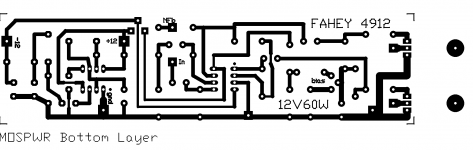
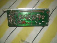
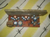
This is the PCB (2002 upgraded version)
Click the image to open in full size.
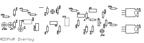
This is the Top Overlay (Parts Layout)
http://img851.imageshack.us/img851/3...pwroverlay.png
It includes a 555 power oscillator inverter to get the -12V rail (actually 10/11V) for the Op Amp, which is a classic TL072.
The amp includes NFB from the speaker terminals, to provide *some* dmping and lower distortion to a bearable level.
Not Hi Fi by any means, but provided *LOUD* 60W RMS without "exotic" (way back then) converters,
Still a lot of them working , generally at Tourist spots, where AC power is unavailable or impractical (Public Squares, Beaches, Subway Stations, etc.)
jm2c
warm regards
andrew lebon
I have not only designed a similar amplifier: a dual Op Amp driving a pair of Push-Pull MosFets, output transformer coupled, but I did it around 1996, commercially producing and selling them in somewhat great numbers (around 100 units).
And even so, I do not claim having had the idea "out of the blue".
I was somewhat inspired by Music Man guitar amps, which uniquely cathode drive 2 or 4 output tubes, with two very high beta power transistors, which in due time are driven by a couple Op Amps.
I thought that a MosFet was, in a way , "the tube and the high beta bipolar all-in-one" equivalent.
Breadboarding proved the validity of the concept.
No Simulation Software way back then, at least none available for me in Argentina.
Some pictures:
1998 Bass Player, happy with his "unplugged" 60W street amp:
Click the image to open in full size.
2000 Classic Double Bass player , also with 60W Battery Amp.
Click the image to open in full size.
This is the PCB (2002 upgraded version)
Click the image to open in full size.
This is the Top Overlay (Parts Layout)
http://img851.imageshack.us/img851/3...pwroverlay.png
It includes a 555 power oscillator inverter to get the -12V rail (actually 10/11V) for the Op Amp, which is a classic TL072.
The amp includes NFB from the speaker terminals, to provide *some* dmping and lower distortion to a bearable level.
Not Hi Fi by any means, but provided *LOUD* 60W RMS without "exotic" (way back then) converters,
Still a lot of them working , generally at Tourist spots, where AC power is unavailable or impractical (Public Squares, Beaches, Subway Stations, etc.)
jm2c
warm regards
andrew lebon
Very nice, especially the 555 power inverter.
I have yet another question, which would be better:
Two TDA1560 circuits,
or one TDA7850?
I recently just wanted to build an amp that is powered by a 12v source, since I have a nice big beefy 12v 12amp transformer, and I thought a car amp IC would be perfect.
If the secondary voltage of the 12V transformer is 12VAC, you will get ~16VDC after rectification/filtering. 12Vac*sqr2 - 1Vd = 16Vdc. With 16Vdc, you can use a full bridge output topology and get ~15Vp output, 30Vp-p. Po>50W a 2R, and no output cap needed.
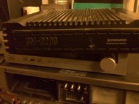
I suspect that the Pioneer will have a converter on board to generate the voltages needed. It all depends on whether you want to build or just buy the gear. There are indeed a range of 12v amp models available for car stereo which are relatively cheap. BUt some specifications quote peak output power for two channels i.e. four times the sinewave (rms) output.
Your transformer might be rated at 12A but when rectified you will get about 18V peak D.C. and the current output at that level would not be 12 A but more like 8A.
At risk of sounding expensive, I would try to get an input filter choke so that you could run a converter at 12V/12A, but a 12A choke would be big and expensive too. BUt it is a good way to "keep the amps and volts". The choke needed for a choke-input power supply would have to be 1 mH - doesn't sound much but 12A wire is heavy. This value is a minimum for max loading - at light loads it would not regulate, (the voltage would go up to 18V again) so you could haver a 10 mH or bigger for better regulation. IF you could get such a component I suspect it would be a good companion to your transformer.
John
- Status
- This old topic is closed. If you want to reopen this topic, contact a moderator using the "Report Post" button.
- Home
- Amplifiers
- Solid State
- the best 12v amp design/project