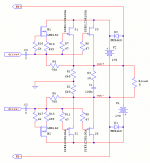
I'm planning a high power mono amplifier (~1.6kW@8ohms) for bass guitar using a direct-coupled floating bridge (circlotron) output stage to use with the new SemiSouth SJEP120R100A power JFETs.

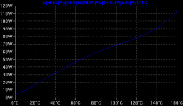
Now armed with an accurate spice model of the device, the device that I don't yet have in my possession, I see that gate threshold voltage drops with increase in temperature making it draw more idle current when it gets hotter.

I missed seeing it in the specs originally and assumed it had a neg tempco from the conductance curves. frack! That first chart is scary.
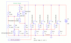
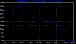
So I came up with this rather complex network around the bleed CCS (see below). Am I just fooling myself that this level of complexity using an NTC and a PTC will accomplish stable idle/overlap/bias current?


I know the real world will be different. heatsink temp a few cm away at the sensors will be different and I'll have to tune the circuit...
But just cause it looks exactly how I want it to behave in the sim, is this complexity too fragile even after tuning and build-to-build as I'm probably going to make four of these amps?
I think I need a topology where the bias current runs a separate path so I'm not assuming a given voltage will equal a given output current. inter-stage transformers are expensive, sigh..

Now armed with an accurate spice model of the device, the device that I don't yet have in my possession, I see that gate threshold voltage drops with increase in temperature making it draw more idle current when it gets hotter.

I missed seeing it in the specs originally and assumed it had a neg tempco from the conductance curves. frack! That first chart is scary.
So I came up with this rather complex network around the bleed CCS (see below). Am I just fooling myself that this level of complexity using an NTC and a PTC will accomplish stable idle/overlap/bias current?


I know the real world will be different. heatsink temp a few cm away at the sensors will be different and I'll have to tune the circuit...
But just cause it looks exactly how I want it to behave in the sim, is this complexity too fragile even after tuning and build-to-build as I'm probably going to make four of these amps?
I think I need a topology where the bias current runs a separate path so I'm not assuming a given voltage will equal a given output current. inter-stage transformers are expensive, sigh..
LND150
hi davygrvy,
I saw your post of the LND150 with a P channel Mosfet to increase the current handling of the CCS for a SV572 SE amp.
Does it Work?
Have you tried this method to increase the current of the LND150 CCS?
Is there any method to use to increase the current capacity of the LND150 without using another depletion mode mosfet with it in a cascode?
- Status
- This old topic is closed. If you want to reopen this topic, contact a moderator using the "Report Post" button.