My Rotel 1062 stopped working in standby, nothing playing, just was dead in the morning.
It keeps blowing the fuses F603 and F604 which are in the output lines of the transformer. Other fuses are fine. They blow immediately when pressing the on switch and the relays switches, no speaker or inputs attached. With help in another thread I got the Service manual with schematics and parts list, but little other descriptions. Weird that it blew without actually amplifying anything. Before I take it apart and test all components I wonder if someone can point me in the right direction about what could cause this behavior? Any help much appreciated.
It keeps blowing the fuses F603 and F604 which are in the output lines of the transformer. Other fuses are fine. They blow immediately when pressing the on switch and the relays switches, no speaker or inputs attached. With help in another thread I got the Service manual with schematics and parts list, but little other descriptions. Weird that it blew without actually amplifying anything. Before I take it apart and test all components I wonder if someone can point me in the right direction about what could cause this behavior? Any help much appreciated.
posting the scehmatic would be a very good place to start
It can be downloaded from here. Download the Rotel RA-1062 service manual for free - Hifi Manuals
It's a three page schematic so it would be hard to load here.
F603 and F604 are the 1st fuses right after the power transformer secondary and pretty much feed everything. 1st suspects will be your power output transistors, power supply cap's and the diode bridge D901.
There is a section that instructs about bias adjustments etc. - but no troubleshooting guide. Isolate the power output section and get the power supply up and running 1st.
I'm saying that's what I would do 1st - not necessarily that there aren't better routs to take. Perhaps there is someone around that knows this amp well and can say - go right over here and do so and so.
Last edited:
Thank you so much will proceed as suggested and see whether I can locate the culprit. D901 is only 90 cents.
Q902 2SB631K-EF $6.20
Q901 2SD600K-EF $ 5
I hope the problem is within that section.
How do I post schematics? Looks like I need an URL but don't see a way to store images here?
Q902 2SB631K-EF $6.20
Q901 2SD600K-EF $ 5
I hope the problem is within that section.
How do I post schematics? Looks like I need an URL but don't see a way to store images here?
How do I post schematics?
I am going to try post these - I don't know if they will come out large enough to be of use tho.

If you bring the image up by clicking in it you can use Ctrl and "+" or "-" to enlarge or shrink the image. Not ideal but looks like it works ok.
Attachments
Last edited:
Thanks, it maybe good enough for the experienced to get an idea. I still hope that someone fixed this problem before or has experience with Rotels. Looks like they are all fairly similar in architecture. A lot of people also try to mod them with better parts. Will take out the transistors and diodes to test on the weekend.
Hi 999 - I'm glad the info helped.
Here are a couple of links to some Rotel forums - I can't vouch for them but with the number of post there should be a few folks that know what they are talking about. Of course there is the probability that there will be some that should be approached with some degree of caution.
Rotel Owner's Thread - Page 10 - AVS Forum
HTGuide Forum - Club Rotel
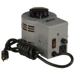
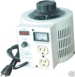
If you found the shot xsistor it seems that you have at least some electronics knowledge and test equipment at hand. Do you have a variable AC transformer on hand (i.e. Variac)? They come in handy when you are firing up electronics equipment because you can limit the amount of voltage and current going to the unit under test and this could save you from smoking sum stuff up!!!
I like the ones that have a current meter on 'em.
Here are a couple of links to some Rotel forums - I can't vouch for them but with the number of post there should be a few folks that know what they are talking about. Of course there is the probability that there will be some that should be approached with some degree of caution.
Rotel Owner's Thread - Page 10 - AVS Forum
HTGuide Forum - Club Rotel
If you found the shot xsistor it seems that you have at least some electronics knowledge and test equipment at hand. Do you have a variable AC transformer on hand (i.e. Variac)? They come in handy when you are firing up electronics equipment because you can limit the amount of voltage and current going to the unit under test and this could save you from smoking sum stuff up!!!
I like the ones that have a current meter on 'em.
Attachments
Last edited:
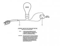
if there's no variac to hand you could hook up a 60w to 100w bulb limiter on the ac primary side so quick checks can be carried out...
That's provided you can still get your hands ON some light bulbs!!!
BTW - if the light bulb goes off like it's the flash unit on a camera - ya got a problem.....
That's provided you can still get your hands ON some light bulbs!!!
BTW - if the light bulb goes off like it's the flash unit on a camera - ya got a problem.....
local shops still do light bulb's...
... some diyer's may not be so lucky to have VR transformers so the next best thing is the light limiter... or they have the popping fuse's each time there faulty unit is powered up...normal test would be on a working amplifier bulb light's as power is applied then settle to a low glow..but if there's a fault it will stay bright
I've not had a bulb blow/pop yet! how ever I still use my 10amp monster vr transformer with build in limiter for such work on monster amps..
let's hope this amplifier get's sort with a good out come
actually, where i work i use a bulb limiter more than i do a variac. it allows me to poke around with a meter without letting the smoke out.
with all of the legismania about incandescent lamps, maybe i should look into getting a spool of nichrome wire to make heater elements to replace the bulbs when they are no longer available.
with all of the legismania about incandescent lamps, maybe i should look into getting a spool of nichrome wire to make heater elements to replace the bulbs when they are no longer available.
Last edited:
Has been a while since I poked around circuits, but we used to build all our amps and speakers back in the day. And yes I had things blow up spectacularly. A variac is certainly a good idea. Took out most txs and diodes and didn't find anything else faulty at this time (I also know why it is expensive to get these things fixed just takes a lot of time doing this carefully).
if there's no variac to hand you could hook up a 60w to 100w bulb limiter on the ac primary side so quick checks can be carried out...
BTW - for those that need to know about this little trick - I found this diagram stuffed in my files - a light bulb limiter..... I think it's been 30 years since I've used one because I got spoiled having a variac around.
We mounted ours on top of an electrical box and light bulb socket and nailed that on top of a piece of wood to keep it from tipping over. After work we would hitch the horse up to the buckboard and head back home. It wuz up hill both ways and the snow wuz always waist high. Oh wait - I'm getting my stories mixed up.
Attachments
Last edited:
home depot has a "fused switch" box with a switch and an edison base socket (the bulb trick predates electronics btw, it used to be how electricians found shorted lines, by screwing a bulb in in place of a fuse). this "fused switch" box is what i have made the last 5 or so limiters. just remove the cover door from the fuse socket and wire this in series with an outlet box.

c2cthomas...I've had my limiter bulb jig for so long that it was made from old 70's disco lamp holder's...built to last..lol. plus I've got my trusty old v/r transformer...the things we've used to aid servicing equipment...
This could be a new tread..service aid pic's...mmm or may that's been covered?
This could be a new tread..service aid pic's...mmm or may that's been covered?
- Status
- This old topic is closed. If you want to reopen this topic, contact a moderator using the "Report Post" button.
- Home
- Amplifiers
- Solid State
- Help with trouble shooting