
Agree on that. For simple, safe and good sounding stuff, Look at DestroyerX ( Carlos') DX amplifier : http://users.tpg.com.au/users/gerskine/dxamp/
Last edited:
There is nothing really wrong with that design at all.
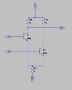
"How about that Q2?"
What about it, it's one have of the diff input pair.
"Can it be pnp?"
It must be the same as Q1, it's one half of the diff input pair.
"Has emitter and collector to be changed?"
No, it's one half of the diff input pair.
"And how about C4 value?"
47µF~100µF would be a good value, with R8 and R9 it's part of the bootstrap CCS for Q3.
R2 bootstraps the input impedance (makes it higher).
This is really a common and ordinary amplifier. Use a 10Ω+0.1µF Zobel on the output to ground (before the fuse).
Now I'm wondering Q1. Where comes its collector current? J
R5 & Base Emmiter of Q3
Doc
that IS the most bizarre way i've seen a diff amp drawn. this looks like something designed for a cheap guitar amp or a console "hi-fi" in the 70's.
btw Q4 in the above schematic is the constant current source for the diff amp. the diodes D4, D5 should be attached to the heat sink for thermal stability.
as for odd ways of drawing diff amps, i always thought the way they were drawn in some of National Semiconductor's data sheets was rather strange.
Attachments
Last edited:
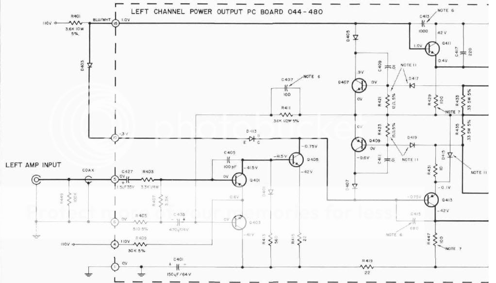
An infinitely high voltage rail with an infinitely high value resistor makes a good CCS.
McIntosh always used very high voltages for their LTP, their preamps are the same way. The Vas also uses a high value resistor to a high voltage rail.
This is good practice, but most people will not have seen a CCS done this way (or the schematics drawn this way).
McIntosh always used very high voltages for their LTP, their preamps are the same way. The Vas also uses a high value resistor to a high voltage rail.
This is good practice, but most people will not have seen a CCS done this way (or the schematics drawn this way).
- Status
- This old topic is closed. If you want to reopen this topic, contact a moderator using the "Report Post" button.
- Home
- Amplifiers
- Solid State
- What is sucking in this wiring?