Hi everybody!
I am having some trouble trying to drive with a 40dB gain stage a passive LP filter feeding another gainstage.
At about 100KHz I can clearly notice that, by increasing the input voltage, although the output of the gainstage has 0 DC offset and is not nearly close to the clipping area, the output at the filter shows a "DC" component.
The signal is all pushed below ground and the more I increase the voltage and the more the signal gests shifted down thus saturating the second stage.
Contrary, if I drive the same filter with my signal generator, as expected, there is no shift at the output of the filter nor at the output of the second stage.
The output of the first stage is capable of driving 10-12mA into the load.
I am wondering if anybody has a clue of what this shift could be caused by and wants to share a thought with me.
Thanks to all for your attention.
Hi everybody!
..
The output of the first stage is capable of driving 10-12mA into the load.
..
Thanks to all for your attention.
Is the driver stage capable of the same current in each polarity?
Is this an overload/over-current effect?
Is the power supply impedance (local decoupling at the driver stage) poor?
interesting points:
1) driving capability is symmetric
2) I am not sure what you meant here
3) power supply has decoupliung by the gain stage and scoping the PSU shows a residual noise under 100uV
I forgot to meantion that if I replace the capacitor with the equivalent impedance (only the resistive value at least) at the specific frequency, the offset disappears.
I think this should sort out any driving or eventual asymmetry problem.
Thank you very much dhaen for your input, if you have any further thoughts please feel free to post them.
Hi Stefano,
By point 2, I meant that perhaps the driving circuit becomes asymmetric at the point of overload. In particular, even an opamp with symmetrical output topology will probably have an asymmetrical input topology, thus if there is any "funny business" (point 3) on the supply rails, it could create an asymmetrical output.
Replacing the reactive load with a resistive load for testing can be misleading. Look at the many audio amps that measure well into resistive loads!
....I'm only brainstorming")
By point 2, I meant that perhaps the driving circuit becomes asymmetric at the point of overload. In particular, even an opamp with symmetrical output topology will probably have an asymmetrical input topology, thus if there is any "funny business" (point 3) on the supply rails, it could create an asymmetrical output.
Replacing the reactive load with a resistive load for testing can be misleading. Look at the many audio amps that measure well into resistive loads!
....I'm only brainstorming
Hi Stefano,
By point 2, I meant that perhaps the driving circuit becomes asymmetric at the point of overload. In particular, even an opamp with symmetrical output topology will probably have an asymmetrical input topology, thus if there is any "funny business" (point 3) on the supply rails, it could create an asymmetrical output.
Replacing the reactive load with a resistive load for testing can be misleading. Look at the many audio amps that measure well into resistive loads!
....I'm only brainstorming
I see what you are saying.
Nevertheless the POwer supply is really stable and properly decoupled by the gain-stage.
If what you are saying could be the problem:
1) how can I detect the nature of it?
2) wht could be a possible fix?
Thanks.
It's not oscillating.
I did although notice that this behavior starts happening when it gets close to saturation.
My observation is: why wouldn't notice the same thing on resistive load?
How can I prevent this problem assuming is due to asymmetric operation close to sat point? Would matching solve or improve this issue?
In case instead it is sub-oscillation that I am not able to detect, what would be your recommended fix?
I did however try to add a small cap (150pF) across the series feedback resistor and it didn't change at all.
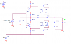
As far as values are concerned, the filter has very low capacitive values. C2 is around 15-22nF while C1 33-45nF. The resistor in series around 50kohm which gives a great isolation thus preventing oscillations and resistor in parallel around 10k.
The stage is biased to accommodate max headroom and sweet spot for the fets.
The stage is biased to accommodate max headroom and sweet spot for the fets.
Another thought...your power supply is +/-28 Volts. The rated Gate-drain breakdown voltage of the 2SJ74 is only 25 volts. You wouldn't have to drive very much output level before you exceeded that for the upper output devices. Have you tried testing the circuit running just +/- 12 Volts?
Could problem be to mismatch of 2sj7 2sk170 input transistors? Small DC error or gain error at summing junction may not be showing up with resistive load, but with capacitor only would drift to match it. Also, maybe gain is non symmetrical due to input capacitance of sources being part of feedback loop. (Hope this makes some sense) Just tossing it out there.
Last question - does (or could) modeling it with spice show up anything?
Last question - does (or could) modeling it with spice show up anything?
Last edited:
Thanks Steve.
Modeling with spice doesn't show anything meaningful with regard to this issue.
I can try to put on selected fets and see what changes. Regarding to the Cgs being part of the fb I need to think better as I am not getting the point.
How would you differently close the loop? I only see one way to do it.
I have a new finding regarding this issue.
If I probe at the output of the filter with a differential probe,the offset at high frequency is no longer there.
I sincerely don't understand why probing with a single ended probe would make a difference in this case
If anybody have any idea feel free to post it.
If I probe at the output of the filter with a differential probe,the offset at high frequency is no longer there.
I sincerely don't understand why probing with a single ended probe would make a difference in this case
If anybody have any idea feel free to post it.
whenever something is that strange, I suspect oscillation. Sometimes, probing makes oscillation worse owing to the excess capacitance. Try isolating the capacitance of the single ended probe by placing 1K between the probe and the point being measured to see if probe loading is causing oscillation.
- Status
- This old topic is closed. If you want to reopen this topic, contact a moderator using the "Report Post" button.
- Home
- Amplifiers
- Solid State
- weird DC offset at HF driving passive filter